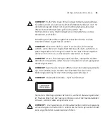
Important Safety Information
47
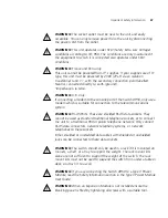
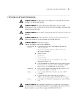
WARNING:
The socket outlet must be near to the unit and easily
accessible. You can only remove power from the unit by disconnecting
the power cord from the outlet.
WARNING:
This unit operates under SELV (Safety Extra Low Voltage)
conditions according to IEC 950. The conditions are only maintained if
the equipment to which it is connected also operates under SELV
conditions.
WARNING:
France and Peru only:
This unit cannot be powered from IT
†
supplies. If your supplies are of IT
type, this unit must be powered by 230V (2P+T) via an isolation
transformer ratio 1:1, with the secondary connection point labelled
Neutral, connected directly to earth (ground).
†
Impédance à la terre.
WARNING:
U.K. only:
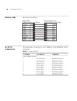
If connecting a modem to the console port of the Switch 4950, only use a
modem which is suitable for connection to the telecommunications
system.
WARNING:
RJ-45 Ports. These are shielded RJ-45 data sockets. They
cannot be used as standard traditional telephone sockets, or to connect
the unit to a traditional PBX or public telephone network. Only connect
RJ-45 data connectors, network telephony systems, or network
telephones to these sockets.
Either shielded or unshielded data cables with shielded or unshielded
jacks can be connected to these data sockets.
WARNING:
The switch should only be used in a rack if it is mounted on
runners, a shelf, or a tray to support the weight. The rack mount kits
alone are not sufficient to support the weight of the switch. The rack
mount kits must not be used to suspend the switch from under a table or
desk, or attach it to a wall.
WARNING:
If you are connecting the Switch 4950 to a Type 3 Power
Module, read the Safety Information section in the Type 3 Power Module
User Guide.
WARNING:
When an Expansion Module is not installed ensure the
blanking panel is fited by tightening all screws with a suitable tool.
Summary of Contents for SuperStack 3 4950
Page 6: ......
Page 18: ...18 CHAPTER 1 INTRODUCING THE SUPERSTACK 3 SWITCH 4950 ...
Page 28: ...28 CHAPTER 2 INSTALLING THE SWITCH ...
Page 44: ...44 CHAPTER 4 PROBLEM SOLVING ...
Page 54: ...54 APPENDIX A SAFETY INFORMATION ...
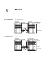
Page 55: ...B PIN OUTS Null Modem Cable 9 pin to RS 232 25 pin PC AT Serial Cable 9 pin to 9 pin ...
Page 58: ...58 APPENDIX B PIN OUTS ...


