background image

Quick Installation Guide

For the SuperStack

®

 II Switch 3900 and Switch 9300 Systems

This guide provides quick procedures for installing one or more of the 
SuperStack

® 

II Switch 3900 and the SuperStack

® 

II


Switch 9300 systems. 

The guide is intended for the network administrator who has experience 
installing communications equipment.

System Setup Tasks

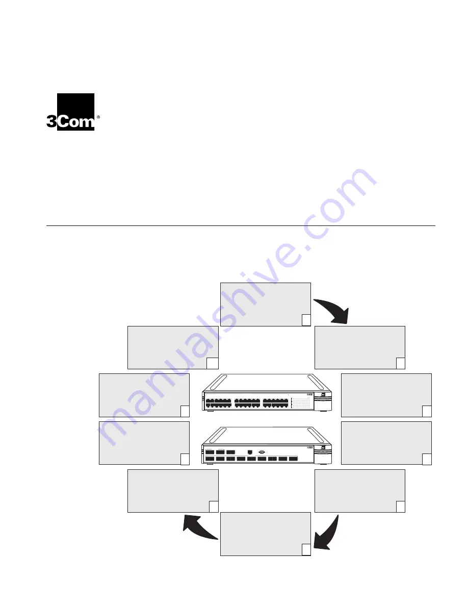
To get your system and its components to the state at which you can 
connect to your network, follow the setup tasks in the figure. If you need 
more information on each setup task, see the related sections in this 
guide or complete details in the indicated documents.

green

=  enabled, link OK

flashing green

=  disabled, link OK

off

= link fail

1000 Base - SX

Super Stack II

Switch 9300

TX

RX

1

1000 Base - SX

10 Base - TX

1000 Base - LX

Console

TX

RX

2

TX

RX

3

TX

RX

4

TX

RX

5

TX

RX

6

TX

RX

7

TX

RX

8

TX

RX

9

TX

RX

10

TX

RX

11

TX

RX

12

Pckt

Stat

Pckt

Stat

Status

Status

1x

6x

12x

7x

13

18

24x

19x

25

30

36x

31x

green

= enabled, link OK

flashing green

= disabled, link OK

off

= link fail

Fault

Power

10/100 BASE - TX

2

3

1

10 11 12

4

5

6

7

8

9

2

3

1

10 11 12

4

5

6

7

8

9

1

1

1

17

1

18 19 20 21 22 23 24

1

1

1

17

1

18 19 20 21 22 23 24

2

2

2

29

2

30 31 32 33 34 35 36

2

2

2

29

2

30 31 32 33 34 35 36

Pckt

Stat

Pckt

Stat

Pckt

Stat

SuperStack

®

 II Switch 3900 (36-port)

SuperStack

®

 II Switch 9300

Install Gigabit Ethernet
Modules (Optional)

(Switch 3900 only)

1000BASE-SX/1000BASE-LX
Gigabit Ethernet Module
Installation Guide

5

6

Attach Cables to the System
and the Optional Modules

Getting Started Guide,

  Chapter  3

Install the Additional
Power Supply (Optional)

Advanced RPS Power Module
Type 2 User Guide

4

Install the System on a
Table Top or in a Rack

Getting Started Guide,
Chapter 2

3

Unpack the SuperStack II
Switch 3900 or 9300 System

Unpacking Instructions

2

Determine Site Requirements

Getting Started Guide,
Appendix B

Software Installation and
Release Notes

1

Administer and Operate
the System

Command Reference Guide and
the

 Implementation Guide

(on the Documentation CD)

10

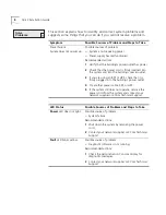
Solve Problems

• This 

Quick Installation Guide

Getting Started Guide, Chapter 6

9

Configure the System for
Management

Getting Started Guide, Chapter 5

8

Power Up the System

Getting Started Guide,
Chapter 4

7

Summary of Contents for SuperStackII Switch 3900

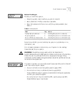
Page 1: ...ff link fail Fault Power 10 100 BASE TX 2 3 1 10 11 12 4 5 6 7 8 9 2 3 1 10 11 12 4 5 6 7 8 9 1 1 1 17 1 18 19 20 21 22 23 24 1 1 1 17 1 18 19 20 21 22 23 24 2 2 2 29 2 30 31 32 33 34 35 36 2 2 2 29 2 30 31 32 33 34 35 36 Pckt Stat Pckt Stat Pckt Stat SuperStack II Switch 3900 36 port SuperStack II Switch 9300 Install Gigabit Ethernet Modules Optional Switch 3900 only 1000BASE SX 1000BASE LX Gigab...

Page 2: ...Switch 9300 system in an area that meets the requirements in Table 1 For more information on site requirements see Appendix B in the Getting Started Guide for your system Check the packing slip to verify that you have all of the components that you ordered The system is shipped with one internal power supply If you have ordered a redundant power supply or uninterruptible power supply for the syste...

Page 3: ...t damage Many installation and troubleshooting procedures should be performed only by trained technical personnel The system operates using a single power supply assembly and is shipped with one internal power supply You can connect an uninterruptible power supply UPS You can also connect a redundant power supply RPS These additional power supplies are orderable and shipped separately Contact your...

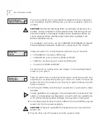
Page 4: ...300 only Console port 3900 and 9300 For information on cabling ports see Chapter 3 in the Getting Started Guide for your system Place the system near an easily accessible power outlet because the only way that you can power the system up or down is to insert or remove the power cord from the power source To get your system powered up and ready to operate 1 For the Switch 3900 verify that each unus...

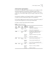
Page 5: ... any have failed diagnostics by checking the module LEDs The system and port LEDs are described in Table 3 Table 3 System and Port LEDs LED Name Type Color Indications Description Power System power Green The system is powered up No light The system is powered down Fault System fault Yellow The system has failed diagnostics or some other operational error has occurred Blinking yellow Diagnostic so...

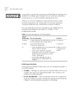
Page 6: ...s over the same network that carries your regular data traffic You configure an IP address on any Ethernet port Out of band 9300 Uses a dedicated network for management data You configure a system management interface for the Ethernet 10BASE T out of band port and assign it an IP address Table 4 System Management Access Mechanisms Access Mechanism Access Description Interface Terminal Connect dire...

Page 7: ...om the top level of the Administration Console enter ip interface define 2 Enter the IP address of the interface 3 Enter the subnet mask Press Return or Enter to accept the default or current value 4 Enter the index number of the VLAN that you want to associate with the IP address For more information about configuring VLANs see the SuperStack II Switch 3900 and Switch 9300 Implementation Guide Ou...

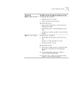
Page 8: ... or UPS check that it is firmly plugged into the building s power outlet 4 Try another power cable RPS or UPS 5 If the system still does not operate remove the power cord from the system and contact your network supplier or 3Com Technical Support LED Status Possible Sources of Problem and Steps to Take Power LED does not light Possible source of problem System failure Recommended actions 1 Shut do...

Page 9: ...panning Tree Contact your network supplier or 3Com Technical Support Stat LED does not light Possible sources of problem System does not recognize a connection to the port Cabling is not fully attached to the port Cabling to the port is faulty Recommended actions 1 Verify that all cables are firmly inserted into both the system s affected port and the attached device 2 Test for faulty cables When ...

Page 10: ...ief description of the problem Some of this information can be viewed in the system display in the Administration Console See the Command Reference Guide for more information For information on where to call see the Technical Support section of the Software Installation and Release Notes or the 3Com Web site www 3com com For information on how to administer and operate the SuperStack II Switch 390...

Page 11: ......

Page 12: ...ide notification of such revision or change 3Com Corporation provides this documentation without warranty term or condition of any kind either implied or expressed including but not limited to the implied warranties terms or conditions of merchantability satisfactory quality and fitness for a particular purpose 3Com may make improvements or changes in the product s and or the program s described i...

Reviews: