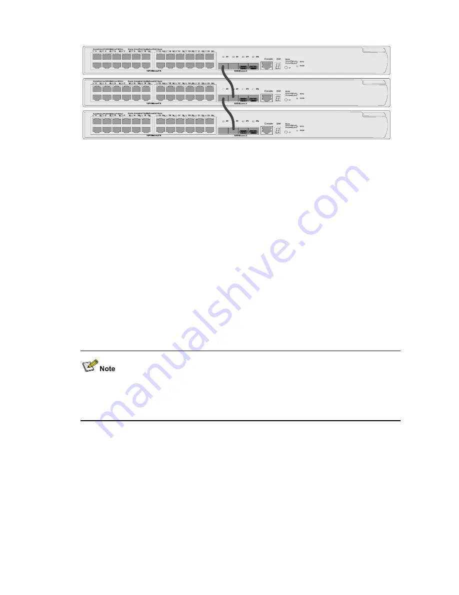
1-2
Figure 1-2
Port connection mode for Switch 4500 series bus topology XRN fabric
Mode
Green=Speed
Yellow=Duplex
RPS
PWR
Console
Unit
1000
Base
-
X
1
Speed
:
Green=100Mbps
,
Yellow=10Mbps
2
3
4
5
6
7
8
9
10
11
12
13
14
15
16
17
18
19 20
21
22
23
24
25
26
27
28
Duplx
:
Green=Full Duplx
,
Yellow=Half Duplx
H3C S3600
Series
10/100Base-TX
Mode
Green=Speed
Yellow=Duplex
RPS
PWR
Console
Unit
1000
Base
-
X
1
Speed
:
Green=100Mbps
,
Yellow=10Mbps
2
3
4
5
6
7
8
9
10
11
12
13
14
15
16
17
18
19 20
21
22
23
24
25
26
27
28
Duplx
:
Green=Full Duplx
,
Yellow=Half Duplx
H3C S3600
Series
10/100Base-TX
Mode
Green=Speed
Yellow=Duplex
RPS
PWR
Console
Unit
1000
Base
-
X
1
Speed
:
Green=100Mbps
,
Yellow=10Mbps
2
3
4
5
6
7
8
9
10
11
12
13
14
15
16
17
18
19 20
21
22
23
24
25
26
27
28
Duplx
:
Green=Full Duplx
,
Yellow=Half Duplx
H3C S3600
Series
10/100Base-TX
Fabric ports
On a Switch 4500-26Port (Switch 4500-50Port) series Ethernet switch, only four GigabitEthernet ports
can be configured as fabric ports. If not used for fabric connection, these four ports can be used as
general data ports. The four ports fall into two groups according to their port numbers:
z
GigabitEthernet 1/0/25(49) and GigabitEthernet 1/0/26(50) form the first group.
z
GigabitEthernet 1/0/27(51) and GigabitEthernet 1/0/28(52) form the second group.
Only one group of ports can be configured as fabric ports at a time. Given a group, either
GigabitEthernet 1/0/25(49) or GigabitEthernet 1/0/27(51) can be configured as the left fabric port, and
either GigabitEthernet 1/0/26(50) or GigabitEthernet 1/0/28(52) can be configured as the right fabric
port.
Once you configure a port as a fabric port, the group that comprises this fabric port becomes the fabric
port group, and you cannot configure a port in the other group as a fabric port. For example, once you
configure GigabitEthernet 1/0/25 as a fabric port, this port automatically becomes the left port and the
first group becomes the fabric port group.
The system does not require a consistency in the fabric port groups between different switches. That is,
the left fabric port in the first group of a switch can be connected to the right fabric port in the second
group of the peer switch.
FTM
As the basis of the XRN function, the Fabric Topology Management (FTM) program manages and
maintains the entire topology of a fabric.
With fabric ports configured, the FTM program releases information of the device through the fabric
ports. The device information includes Unit ID, CPU MAC, device type ID, fabric port information, and all
fabric configuration information. The device information is released in the discovery packet (DISC).
After receiving the packet, the peer device will analyze the packet. A device can form a fabric with the
peer or join a fabric only when the following conditions are met.


