39-27
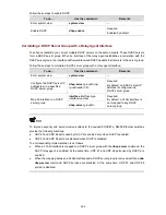
To do…
Use the command…
Remarks
Display lease expiration
information
display dhcp server expired
{
ip
ip-address
|
pool
[
pool-name
] |
interface
[
interface-type
interface-number
] |
all
}
Display the free IP addresses
display dhcp server free-ip
Display information about
address binding
display dhcp server ip-in-use
{
ip
ip-address
|
pool
[
pool-name
] |
interface
[
interface-type
interface-number
] |
all
}
Display the statistics on a
DHCP server
display dhcp server statistics
Display information about
DHCP address pool tree
display dhcp server tree
{
pool
[
pool-name
] |
interface
[
interface-type interface-number
] |
all
}
Clear IP address conflict
statistics
reset dhcp server conflict
{
all
|
ip
ip-address
}
Clear dynamic address binding
information
reset dhcp server ip-in-use
{
ip ip-address |
pool
[
pool-name
] |
interface
[
interface-type
interface-number
]
| all
}
Clear the statistics on a DHCP
server
reset dhcp server statistics
Available in
user view
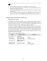
Executing the
save
command will not save the lease information on a DHCP server to the flash
memory. Therefore, the configuration file contains no lease information after the DHCP server restarts
or you clear the lease information by executing the
reset dhcp server ip-in-use
command. In this case,
any lease-update requests will be denied, and the clients must apply for IP addresses again.
DHCP Server Configuration Examples
Currently, DHCP networking can be implemented in two ways. One is to deploy the DHCP server and
DHCP clients in the same network segment. This enables the clients to communicate with the server
directly. The other is to deploy the DHCP server and DHCP clients in different network segments. In this
case, IP address assigning is carried out through DHCP relay agent. Note that DHCP server
configuration is the same in both scenarios.
DHCP Server Configuration Example
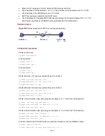
Network requirements
z
The DHCP server (Switch A) assigns IP address to clients in subnet 10.1.1.0/24, which is
subnetted into 10.1.1.0/25 and 10.1.1.128/25.
z
The IP addresses of VLAN-interface 1 and VLAN-interface 2 on Switch A are 10.1.1.1/25 and
10.1.1.129/25 respectively.


