Lay
ration Example
N
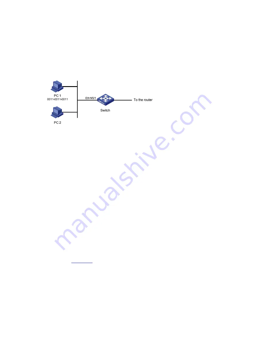
1/0/1. PC 1’s MAC address is 0011-0011-0011.
ss of 0011-0011-0011 and the destination
.
er 2 ACL Configu
etwork requirements
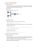
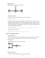
PC 1 and PC 2 connect to the switch through Ethernet
Apply an ACL to filter packets with the source MAC addre
MAC address of 0011-0011-0012 from 8:00 to 18:00 everyday
Network diagram
Figure 44-5
Network diagram for Layer 2 ACL
Configuration procedure
daily
the source MAC address of 0011-0011-0011 and the destination
eny source 0011-0011-0011 ffff-ffff-ffff dest
est
rame-4000] quit
User-
nts
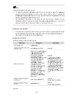
# Define a periodic time range that is active from 8:00 to 18:00 everyday.
<Sysname> system-view
[Sysname] time-range test 8:00 to 18:00
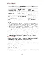
# Define ACL 4000 to filter packets with
MAC address of 0011-0011-0012.
[Sysname] acl number 4000
[Sysname-acl-ethernetframe-4000] rule 1 d
0011-0011-0012 ffff-ffff-ffff time-range t
[Sysname-acl-ethernetf
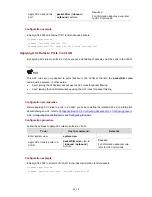
# Apply ACL 4000 on Ethernet 1/0/1.
[Sysname] interface Ethernet1/0/1
[Sysname-Ethernet1/0/1] packet-filter inbound link-group 4000
defined ACL Configuration Example
Network requireme
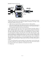
As shown in
Figure 44-6
, PC 1 and PC 2 are conn
Ethernet 1/0/2 respectively. They belong to VLAN
ected to the switch through Ethernet 1/0/1 and
1 and access the Internet through the same gateway,
ss of VLAN-interface 1).
ckets from PC 1 that use the gateway IP address as
which has an IP address of 192.168.0.1 (the IP addre
Configure a user-defined ACL to deny all ARP pa
the source address from 8:00 to 18:00 everyday.
44-17


