1.
2.
3.
4.
5.
6.
1.
2.
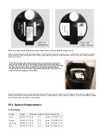
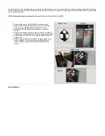
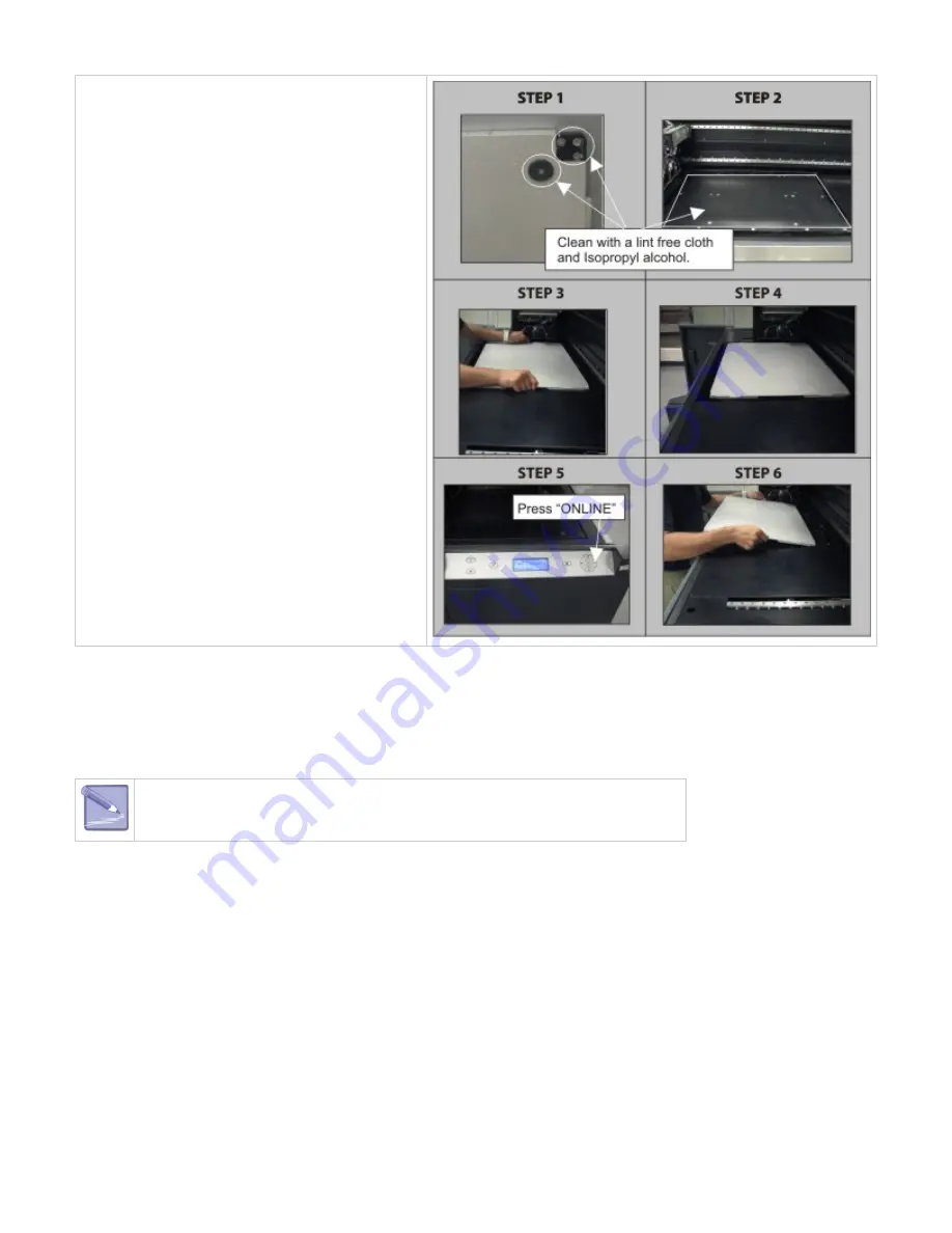
Ensure that the corner guides on the backside of
platform are clean and free of debris. If debris exists
when installing, the platform guides will not lock into
the platform elevator.
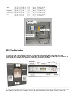
Clean platform elevator and platform using a lint free
cloth and Isopropyl alcohol. When cleaning platform,
clean the front and back sides.*
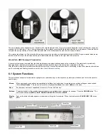
Lift build chamber door; place platform with corner
guides and pads facing down onto the platform
elevator. Seat onto elevator. The corner guides will
affix the platform to the elevator and if properly
installed, platform will not move.
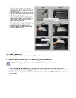
Ensure platform sits squarely on the elevator and is
firmly located by the corner guides. Use caution not
to drop the platform or hit the printhead.
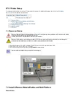
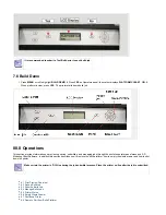
Close build chamber door and press ONLINE.
To remove platform, lift from the sides; pull up and
out from the platform elevator.
7.2.1 MDM Installation
Please click on the link to access the installation instructions:
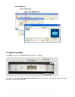
7.3 Install and Run ProJet™ 3-D Modeling Client Software
NOTE: Before installing software, ensure network and PC meet
requirements.
Load the
from CD packaged with the printer's accessories kit. An autorun file on the CD will
3-D Modeling Client Software
automatically load when CD is inserted into ROM drive of the computer. If installation program does not start when loaded, select and
run
from the root directory of the ROM drive.
Setup.exe
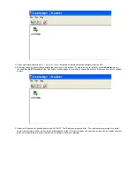
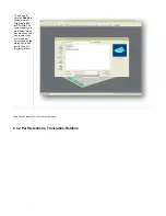
After successfully installing software, select
from the
menu and then select >
icon. The printer
Start
Program
3-D Modeling Client
window appears.
Summary of Contents for ProJet 5000
Page 34: ...This view point button is a back two dimensional viewpoint Bottom View ...
Page 36: ...A bounding box for a set of objects is a cuboid that completely contains the set Copy ...
Page 41: ...This view point button is a front two dimensional viewpoint Help Topics ...
Page 45: ...This view point button is a right two dimensional viewpoint Rotate ...
Page 60: ...Using a wire frame allows visualization of the underlying design structure of a part Zoom ...

