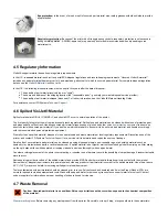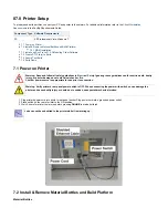
The part material used to build parts is an ultraviolet (UV) curable material. After a layer of material is deposited in the build chamber, the part is
exposed to a UV flash lamp. The UV energy is absorbed by the material converting the liquid build material to a solid polymer. When the build is
complete the part (consisting of the two materials) is adhered to the build platform by means of the support material.
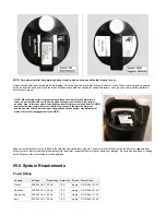
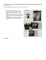
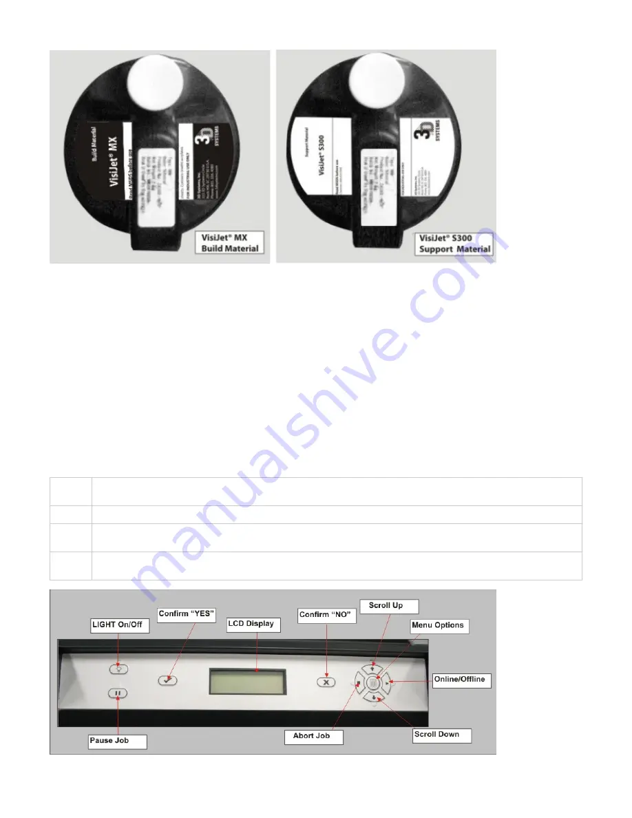
The material is delivered in a 2kg. plastic bottle and are placed in the machine's material delivery module (MDM). Support material modules are
located on the left side of the machine and the part material modules are located on the right side of the machine.
Waste Path, HMS Cleaning & Planerization
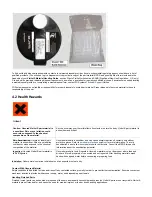
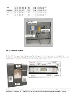
A vacuum system draws the waste from the head maintenance and planerization operations to a waste tank. The waste tank is periodically
discharged into a waste bag for disposal. A curing light resides above the bag to cure the top layer of material in the bag.
After the build is complete, the platform and the part are removed. A secondary operation, known as finishing, is required to provide a finish/clean
part. For cleaning and finishing instructions, refer to the
6.1 System Functions
The instructions use special text formats to highlight menu commands, keys on the keyboard, operator panel buttons, and text on the operator
panel display.
Menus:
Menu names and menu options are capitalized in boldface text. Instructions for selecting menu options will appear as described:
"Select
." This means "select (click or highlight) the
, then select
on the menu.
Menu>Option
Menu
Option
Keys:
Keyboard key names are capitalized; for example, "Press the Enter key."
Buttons:
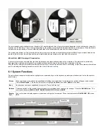
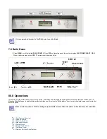
Command buttons on the modeler's operator panel are in boldface upper case text; for example, "Press the
button." The
ONLINE
command buttons are:
,
,
,
,
,
, and
.
MENU LIGHT PAUSE ONLINE YES NO
ABORT
Display
:
Text:
Text on the printer's display appears in uppercase in this guide; for example, "When the display shows
?
, press
PAUSE JOB Y/N
.
YES
Summary of Contents for ProJet 5000
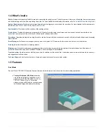
Page 34: ...This view point button is a back two dimensional viewpoint Bottom View ...
Page 36: ...A bounding box for a set of objects is a cuboid that completely contains the set Copy ...
Page 41: ...This view point button is a front two dimensional viewpoint Help Topics ...
Page 45: ...This view point button is a right two dimensional viewpoint Rotate ...
Page 60: ...Using a wire frame allows visualization of the underlying design structure of a part Zoom ...


