1.
2.
3.
07.0 Printer Setup
To prepare and build part files, connect your PC and printer to the network. For additional information refer to the
in the Facility Requirements Guide.
Component Type
Software Requirements
PC
XP Professional, Vista, Windows 7
7.1 Power on Printer
7.2 Install & Remove Material Bottles and Build Platform
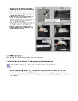
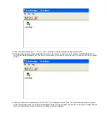
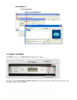
7.3 Install and Run ProJet™ 3-D Modeling Client Software
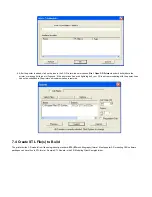
7.4 Create STL File(s) to Build
7.5 Submit Test Build
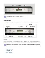
7.6 Build Demo
7.1 Power on Printer
Warning: Read and follow all safety guidelines in
. Ignoring these guidelines could result in death, bodily
injury, or printer damage due to electrical shock or fire.
Confirm power source is appropriate for use prior to connection.
Warning: Verify printer's rear panel power switch is OFF. When connecting the power with switch on can damage the
printer and cause bodily injury or death due to sudden, unexpected mechanical motion.
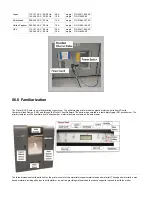
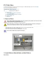
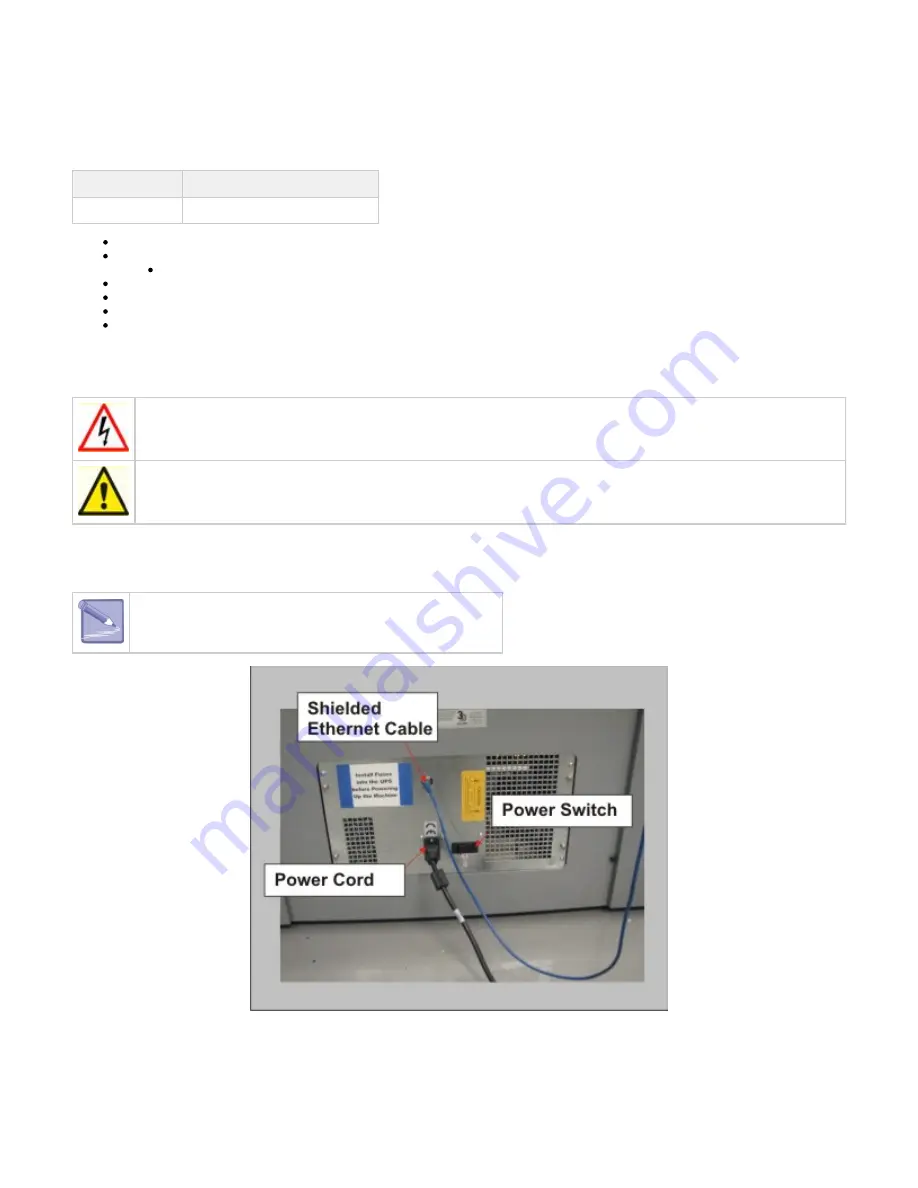
Plug printer's power cord into printer's rear panel socket. Plug power cord into a grounded power outlet.
Place switch on the rear of printer to the ON position.
Wait 4 hours for printer to warm up before pressing
to start a build job.
ONLINE
Jobs can not be submitted to the printer while it is warming up.
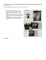
7.2 Install & Remove Material Bottles and Build Platform
Material Bottles
Summary of Contents for ProJet 5000
Page 34: ...This view point button is a back two dimensional viewpoint Bottom View ...
Page 36: ...A bounding box for a set of objects is a cuboid that completely contains the set Copy ...
Page 41: ...This view point button is a front two dimensional viewpoint Help Topics ...
Page 45: ...This view point button is a right two dimensional viewpoint Rotate ...
Page 60: ...Using a wire frame allows visualization of the underlying design structure of a part Zoom ...

