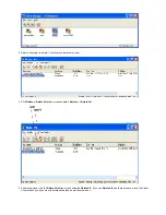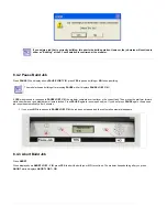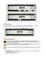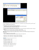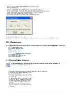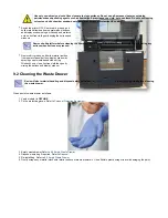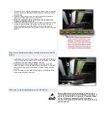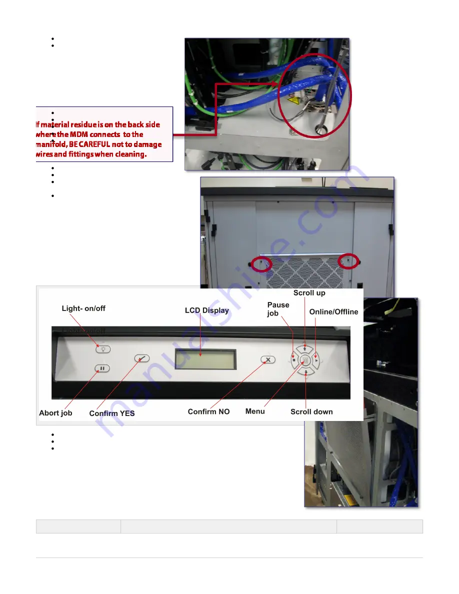
Pull fan out and discard.
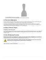
Install new fan filter and secure fan panel turning the two thumb screws clockwise.
9.8 Printhead Maintenance
The printhead will need to be cleaned after every build. The client software consist of a printhead maintenance mode (PH Maintenance).
To access the PH Maintenance Mode:
Close chamber door.
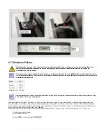
Press the menu button and scroll up or down until PH Maintenance appears; select yes to confirm.
The X and Y axis will move into their home positions; the Z Axis will move down.
Once axis are in their home positions, a click will sound from the chamber door indicating the door can be opened.
Remove the front panel from the printer by loosening the thumb screw and disconnecting the ground strap from the panel. Lift panel out and carefully place it aside.
Use caution when doing maintenance on the printhead and planerizer. These areas are heated and can be hot.
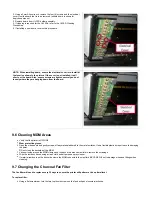
Visually inspect the UV LEDS to ensure they do not need replacing or if they are clean. If cleaning is required, see the UVLED CLEANING PROCEDURE for proper cleaning instructions. If replacement is necessary, see UVLED REPLACEMENT PROCEDURE.
Clean areas where materials debris may have accumulated.
Inspect the planerizer for damage. Also, wipe the
planerizer roller using a lint free cloth and acetone.
Clean the printhead's array plate using a lint free
cloth and acetone. Ensure that it is sufficiently
cleaned and that there are no drips left on plate.
10.0 Error Messages
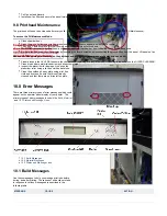
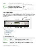
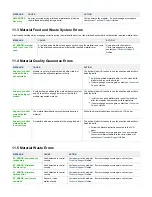
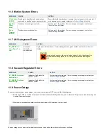
There are three primary types of error messages which could
appear on the operator panel display of your printer. The
primary types of error messages found will be
, and
.
10.1 Build Messages
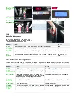
10.2 Material Messages
10.3 Status and Message Lines
10.1 Build Messages
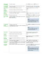
Use these messages to help you manage print jobs before,
during, and after printing. The causes of and actions to take
in response to various messages are described in the
following table:
MESSAGE
CAUSE
ACTION
Summary of Contents for ProJet 5000
Page 34: ...This view point button is a back two dimensional viewpoint Bottom View ...
Page 36: ...A bounding box for a set of objects is a cuboid that completely contains the set Copy ...
Page 41: ...This view point button is a front two dimensional viewpoint Help Topics ...
Page 45: ...This view point button is a right two dimensional viewpoint Rotate ...
Page 60: ...Using a wire frame allows visualization of the underlying design structure of a part Zoom ...


