


BFB-3000 Set Up and Operations Manual
Document No: D100253
24
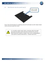
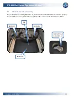
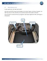
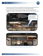
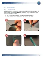
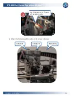
Adjust the height of the bed bolts to make each side level using the 3mm hex driver
from the toolkit.
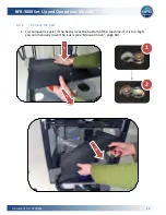
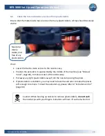
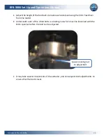
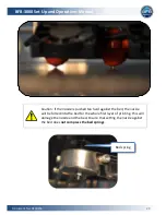
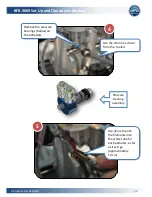
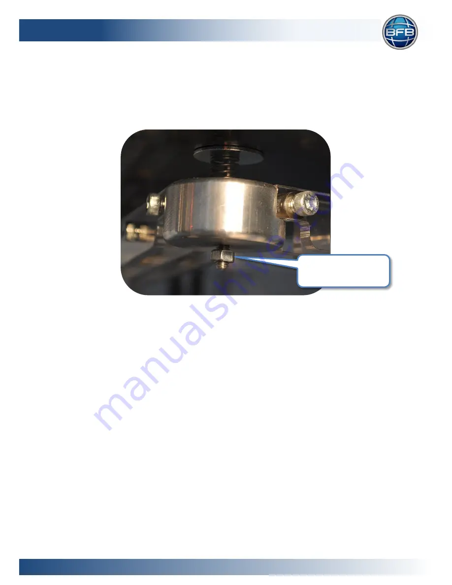
Underneath each of the 3 bed bolts is a locking nut which must be loosened with the
8mm spanner before the bolt can be adjusted.
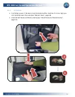
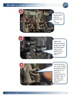
It may take several movements of the extruder, and consequent bolt adjustments to
ensure that the bed is level.
Loosen locking nut
to adjust bolt.


