background image

55

3D Systems, Inc

.

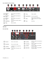
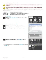
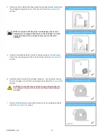
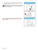
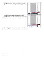
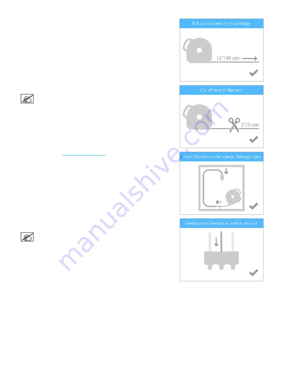
8 .  Pull out 12”/30 cm of material from the cartridge . Select the 

checkmark

 to 

continue .

9 .  Cut off 2”/5 cm of material from the end . Select the 

checkmark

 to continue .

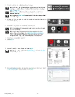
NOTE: Ensure the material is not bent or creased . If the material is 

not straight, pull out the damaged material from the cartridge . Cut 

off and dispose the portion that is damaged .

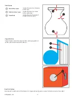
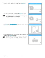
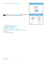
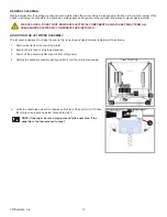
10 .  Insert the material 

under the clamp roller

 and into the material tube . Select the 

checkmark

 to continue .

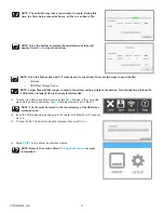
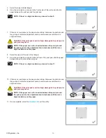
11 .  Gently push the material into the print jet until molten plastic extrudes into the jet 

wiper . Select the 

checkmark

 to continue .

NOTE: When the material reaches far enough into the print jet area, 

a feed motor will assist with feeding the material into the print jet .

Summary of Contents for CubePro

Page 1: ...CubePro User Guide Original Instructions Prosumer 3D Printer ...

Page 2: ... REQUIREMENTS 6 Dimensions and Weight 6 Weight and Dimensions 6 PC Requirements 6 Software 6 Electrical Requirements 6 Material Storage 6 6 UNPACKING AND SETTING UP YOUR CUBEPRO 7 Contents 7 Unpacking and Setting Up Your CubePro 8 Setup and Activate Your CubePro 14 Menu Overview 18 Touchscreen Display 18 Print Setup 18 Navigation 18 Materials 18 Cartridge Status 18 Change Cartridge 18 System 19 Se...

Page 3: ...oftware 36 Installing Mac Software 37 CubePro Software Overview 39 Home Tab 39 CAD File Functions 40 Geometry Functions 40 Color Build Print File and Help 41 View Tab 41 Zoom and View 41 Print Paths 42 Settings Tab 42 Printer Configuration 43 Build Settings 44 Descriptions 45 Firmware Update 48 Printer Connection 48 Preparing and Printing a Creation 49 10 OPERATION PROCEDURES 52 Applying Cube Glue...

Page 4: ...ration Print 68 Calibrating the Offset Jets 69 Calibration Overview 69 Reading the Offset Jets Scale 70 Offset Jets Calibration Procedure 71 Calibrating the Wipe Function 74 Testing the Print Jets and Extruders 74 Moving the Print Jets 76 Updating the CubePro Firmware 77 Updating Firmware Using USB 77 Updating Firmware Using WI FI 78 Replace Fuses 81 Error Codes 83 Material Flow Errors 83 Temperat...

Page 5: ... under the normal conditions described in the documentation provided to you including this User Guide 3D Systems will promptly repair or replace the CubePro 3D Printer if required to make it free of defects during the warranty period This warranty excludes i normal consumable or expendable parts such as Material Cartridges ii repairs required during the warranty period because of abnormal use or c...

Page 6: ...EP FINGERS AND OTHER BODY PARTS AWAY HOT SURFACE HAZARD DO NOT TOUCH THE PRINT JETS DURING SETUP AND OPERATION THE PRINT JETS BECOME VERY HOT Caution Read and follow all instruction prior to setting up the printer SHOCK WARNING DUE TO RISK OF SHOCK AVOID CONTACT WITH ALL INTERNAL ELECTRONIC COMPONENTS WARNING THE CUBEPRO SHOULD ONLY BE SERVICED BY AUTHORIZED SERVICE TECHNICIANS PRIOR TO ANY PART R...

Page 7: ... using an Ultrasonic Support Removal Tank available at http cubify com en Products CubeXSupplies PRINT MATERIALS The CubePro can use two different types of print materials PLA and ABS Each material has unique benefits and you can guide your selection based on the properties your part requires PLA This is a hard plastic that has a low environmental impact It is derived from renewable starch based r...

Page 8: ...Locations of important areas are the same for the CubePro and CubePro Duo A Removable Top Cover B Touchscreen Display C Touchscreen On Off Button D Fuses E Printer Power Switch F Power Inlet Port G USB Inlet Port H Printer USB Port A B C D E G H A Print Jet 1 B Print Jet 2 C Print Jet 3 D Jet Wiper Assembly E Material Cartridge 1 F Print Chamber Heater G Print Plate H Print Pad I Material Cartridg...

Page 9: ...ond and third cartridge bays of a CubePro Trio A Material Tube B Clamp Rollers C Cartridge Recognition Connections D Material Cartridge Bay 2 Hinge E Material Cartridge Mount Rings F Material Cartridge Bay 2 G Material Cartridge Bay 3 A B C D E F G View From Top ...

Page 10: ...ion with Service Pack 3 or higher software CubePro conversion software is available at www Cubify com Multi core processor 2GHz or faster per core System RAM 2GB Screen resolution 1024 x 768 dpi SOFTWARE CubePro Client Software Available at www Cubify com ELECTRICAL REQUIREMENTS 100 240V AC 50 60 Hz auto switching 6A MATERIAL STORAGE Although all polymers degrade with time the following conditions...

Page 11: ... configuration NOTE The appearance of some components may vary Material cartridge Cube Glue x2 Jet Wiper Power cord Print pad CubePro printer Wire Cutters Print Pad Cleaner scraper Needle Nose Pliers Wrench 8 mm Sandpaper Hex Drivers 2 5mm 3mm and 4mm T Handle T10 Torx Toolkit USB Stick Cubify Invent License Code ...

Page 12: ...inter to its final location NOTE Ensure that you save all foam and packing material for the future repacking of your CubePro Shipping the printer without original packing materials may cause damage to the printer 1 Carefully cut the straps A and then pull the tabs B on all four release clips NOTE There is one release clip on each side of the box 2 Pull the handles A and remove the release clips fr...

Page 13: ...9 3D Systems Inc 3 Lift the box away from the printer 4 Remove the accessories tray ...

Page 14: ...print pad box from the upper foam support and set it aside CAUTION The print pad is fragile Exercise caution when handling the print pad 6 Remove the upper foam support from the top of the printer 7 Remove the foam corner protectors ...

Page 15: ...e printer where it will be used NOTE Ensure the printer is placed in a location where its size and weight will be properly supported 10 Verify the contents in the accessories tray The boxes contain the following tool kit A 1 3 print cartridges B depending on the printer configuration jet wiper and glue bottles C and power cord D A B C D B B ...

Page 16: ...screws for future repacking 13 Using a 4mm hex head driver attach the mounting posts to the jet wiper assembly with the supplied screws and washers NOTE Tighten the screws until the posts are secure 14 Move the jet wiper assembly to the back of the printer and locate the keyhole slots A 15 Mount the jet wiper mounting posts to the back panel of the printer through the keyhole slots NOTE Slide the ...

Page 17: ...g clockwise NOTE Refer to the section titled Adjusting the Jet Wiper Assembly for information about adjusting the jet wiper scraper height 17 Remove the print pad from the box and place it onto the print platform with the round magnet on the bottom of the pad inserted into the triangular opening on the platform Ensure the print pad is securely seated on the print plate 18 Connect the power cord to...

Page 18: ... 3 Connect your printer to your wireless network Use the up or down arrow to scroll to your network choice Select the checkmark to continue NOTE If your network is password protected the printer will first prompt you to enter the password NOTE The printer can also connect to an ad hoc network a decentralized network that wirelessly connects a local computer to the printer directly The computer mus...

Page 19: ...checkmark to continue the warranty activation process NOTE You must create a Cubify account to activate the printer 5 To create a Cubify account go to www cubify com and select My Cubify Select Create an Account and enter the registration information 6 Log in to Cubify com Go to www cubify com and select My Cubify Enter your username and password and select Login 7 Select CubePro from the Products...

Page 20: ... label adhered to the right side of the printer near the power on off switch NOTE Your 4 digit activation code will appear Please note the activation code because it will need to be entered into the printer s touchscreen display to activate the printer NOTE You can access the User Guide software for either Windows or Apple operating systems and free creations 10 Select the checkmark to continue ...

Page 21: ...ivation process enter your 4 digit code in the touchscreen display Select the checkmark to continue NOTE If the wrong activation code was entered select RETRY and enter the activation code again 12 Select the checkmark to complete the activation process Your printer is now ready to print a creation ...

Page 22: ...ePro software You can invent your own creation by using Cubify Invent software available at www Cubify com SETUP allows the user to configure the printer connect to a wireless or ad hoc network install cartridges or view the printer status NAVIGATION Navigation between screens is performed by pressing the right or left arrows MATERIALS Cartridge Status CARTRIDGE STATUS allows the user to view the ...

Page 23: ...er will display the printer status including the serial number the print jet temperatures and the name of the wireless network to which the printer is connected NETWORK The Network menu allows the user to connect to a wireless network or to an ad hoc device PRINT JET CALIBRATION The print jets in the CubePro are calibrated from the factory and should not need to be recalibrated The Print Jet Calib...

Page 24: ...he printer If the printer recognizes that no cartridge has been installed the display will prompt you to install the appropriate cartridge 1 Select INSTALL CARTRIDGES 2 Select the cartridge to be installed NOTE The print jet will begin to heat 3 Open the packaging and remove the thumbscrew from the new cartridge Select the checkmark to continue ...

Page 25: ... out the damaged material from the cartridge Cut off and dispose the portion that is not straight 6 Insert the material under the clamp roller and into the material tube Select the checkmark to continue 7 Gently push the print material into the print jet until molten plastic jets into the jet wiper Select the checkmark to continue NOTE When the material reaches far enough into the print jet area a...

Page 26: ...idge A where the material exits is seated under the clamp roller and between the vertical alignment pins in the cartridge bay CAUTION If replacing the third cartridge be sure to rotate the second bay cartridge to its vertical position before selecting the checkmark NOTE The print pad must be calibrated before printing your first creation For more information refer to the following section titled C...

Page 27: ...e and select PRINT 5 Apply two thin layers of Cube Glue to the print pad in an area of 50 mm x 50 mm Select the checkmark to continue NOTE For more information refer to the section titled Applying Cube Glue NOTE It may take about five 5 minutes to print the file 6 When finished remove the print pad and verify the calibration NOTE Refer to the section titled Reading The Calibration Print NOTE If an...

Page 28: ...e the Z Gap and the Print Pad Level should be verified before printing The Z Gap should be within specifications before adjusting the Level Gap If adjustments to the Z Gap are necessary perform the adjustments and then print the calibration file again to verify the correct Z Gap A correct Z Gap is indicated when there is no gap in the Closed Z Gap measurement and there is a gap in the Open Z Gap m...

Page 29: ...n Z Gap If there is a gap B between the Open Z Gap bars C and the baseline A and there is no gap between the Closed Z Gap bars and the baseline the Z Gap is correct Incorrect Open Z Gap If there is no gap B between the Open Z Gap bars C and the baseline A turn all three 3 print pad adjustment knobs clockwise right 1 step and print the file again to verify that the lines do not touch If they touch ...

Page 30: ...rrect Acceptable Print Pattern The Print Pad Level calibration file should print with no gap between the Print Pad Level calibration lines and the baselines The illustration indicates an acceptable print pattern from a profile view No Gap Unacceptable Print Patterns If the gap between the print pad and the print jet nozzles is too small the Print Pad Level calibration lines will press in and scrap...

Page 31: ...ng on your display press the touchscreen to begin 2 Select PRINT NOTE If the file is saved on a USB mass storage device insert the device into the USB port on the printer NOTE You can also print directly from the CubePro software using a USB cable connecting the printer to the computer or by wireless connection 3 Using the arrows navigate to your file and select PRINT NOTE The file name will be di...

Page 32: ...ed Replacing A Material Cartridge NOTE If there is not enough material in the cartridge to complete the print the printer will prompt the user to replace the cartridge Select CHANGE CARTRIDGE and follow the instructions in the section titled Replacing A Material Cartridge NOTE If the creation file uses color s that are not installed selecting the checkmark will enable the printer to change the col...

Page 33: ...he glue increasing its adhesion NOTE Ensure that the area where glue is applied is larger than the base of your creation NOTE The estimated time to completion is noted at the bottom of the screen NOTE When printing with only ABS material the print chamber will need to build and maintain a predetermined temperature Ensure the top cover and the back panel have been installed The front door must be c...

Page 34: ...lect CANCEL if you wish to cancel the print job NOTE Once printing has been paused select RESUME if you wish to continue printing NOTE To cancel the print job select CANCEL to confirm your decision Otherwise select RESUME to continue printing 5 Once the printer has finished printing select the checkmark to continue ...

Page 35: ... has finished printing CAUTION Do not touch the print jets until they have cooled to room temperature 6 Refer to the section Finishing Your Creation for information about removing your creation from the print pad and the procedure for cleaning the creation and the print pad ...

Page 36: ...t pad before reinstalling it into the printer can damage sensitive electrical components and void the manufacturer s warranty Removing Rafts A raft is the flat support structure that is attached to the base of your creation if you enabled that option when building the cubepro file Though it is recommended that printing be done without a raft some larger more complicated parts may require one ABS R...

Page 37: ...must be positioned on a flat stable work surface Do not tip over or move the tank during its operation Electrical equipment can become damaged when exposed to water or other fluids 1 Pour 0 75 liters 0 79 quarts of water into the tank 2 Place the models to be cleaned into the tank 3 Close the lid 4 Connect the power supply and press the power button to turn on the tank 5 Set the temperature to 80 ...

Page 38: ... the bottom of the tank 4 Immediately clean the measuring bowl and scales to ensure removal of all caustic soda 5 Using plastic tongs and all the recommended personal protection equipment gently lower the model into the caustic soda solution CAUTION Exercise caution so that none of the solution spills 6 Close the lid 7 Connect the power supply and press the power button to turn on the tank 8 For b...

Page 39: ...eaned from the area you may remove your personal protection equipment 15 Repeat the ultrasonic process with clean water for 30 minutes at 60 C to remove any caustic soda residue that may remain on the model 16 Once the ultrasonic process has completed the second time use plastic tongs to remove the model from the ultrasonic tank 17 Rinse it under cold water for 1 to 2 minutes ...

Page 40: ...c operating systems INSTALLING WINDOWS SOFTWARE 1 Go to www Cubify com and log in with your username and password 2 Select CubePro from the Products dropdown menu 3 Select Windows NOTE The software will download as a zipped file 4 Extract the zip file and double click the Windows installer file 5 Read through the End User License Agreement If you accept the terms of the agreement select the accept...

Page 41: ...e software will begin to install NOTE The software installation is complete INSTALLING MAC SOFTWARE 1 Go to www Cubify com and log in with your username and password 2 Select CubePro from the Products dropdown menu 3 Select Mac ...

Page 42: ...38 3D Systems Inc 4 Download the dmg application file to your computer 5 Select the Downloads icon on the Dock and select the CubePro dmg file 6 Drag the CubePro file into the Applications folder ...

Page 43: ... can print Once a cubepro file has been generated this print file can no longer be edited although the original stl file can be used again to create another cubepro file STL Files Files that can be imported and edited prior to building a cubepro file CUBEPRO Files Files that have been prepared sliced into layers and are ready to print NOTE The CubePro software interface for Mac may differ in color...

Page 44: ... D Auto Place Auto Place the model to the center of the print area E Move Model Once this button has been selected left click on the model and drag it into position F Scale Value Field Enter the scale percentage G to mm Scale the 3D model to the millimeter value entered in the field H to Inch Scale the 3D model to the inch value entered in the field I Scale Scale the model by the specified percent...

Page 45: ...int File Save a build print file H Send Send a print job through the wireless network to a connected printer I Help Help menu A Zoom In Zoom in on the model B Zoom Out Zoom out on the model C View Tab Contains Zoom View and Print Path tools D Fit to Window Fit the model to the center of the window E Top View Select the button to view the top of the model F Front View Select the button to view the ...

Page 46: ...ath layers E About Software version and update information link A Settings Tab Adjust the settings B Printer Configuration Set the printer type number of print jets and printer materials C Build Settings View and select the build settings used when creating the tool path for the print file D Firmware Update Update the printer firmware E Printer Connection Setup a wireless connection with the print...

Page 47: ...of print jets in your printer C Print Jet 1 Material Select the type and color of material installed in cartridge bay 1 D Print Jet 2 Material Select the type and color of material installed in cartridge bay 2 E Print Jet 3 Material Select the type and color of material installed in cartridge bay 3 A B C D E ...

Page 48: ... smoothness of a part C Print Strength The strength of the inner structure of a creation D Print Pattern The design of the inner structure of a creation E Raft and Support Selection of the types of materials used to create rafts and supports F Advanced Adjustments to print pattern fill and the creation shell G Help Opens the help menu F A B E C D G ...

Page 49: ... a wide range of geometries Fine detail preservation for things like steeples spires sharp points or thin walls 0 300 A fast mode with thicker layers Good for large parts with minimal detail Print Strength Hollow Fastest mode to produce a part Hollow has fewer outer surfaces and larger print pattern spacing Best for parts that will not be stressed Strong Medium amount of outer surfaces and smaller...

Page 50: ... Build Settings utility allows you to customize the layer thickness of the Print Pattern Fill and the Shell Options Print Pattern Fill Fill Spacing is the amount of space between interior supports Lower values increase the interior strength of the creation ...

Page 51: ... surface layer C Outer Walls Increase the value for increased strength of the outer walls C B A Support Borders Support borders A reinforce supports B for overhanging parts and should not be used for holes and cavities C Draw Fine Features Select enable for small parts with fine features For larger parts needing more accuracy this feature should not be enabled A B C ...

Page 52: ...re Instructions for updating firmware in your CubePro B Download Firmware Download firmware to a mass storage device B C A A Printer Select Select the printer connection B Discover Find an applicable printer on the network C Add Add a printer using the printer s IP address B A ...

Page 53: ...otate the mouse wheel in either direction Rotate the Stage Left click and drag the mouse to change the view of the model Move the Stage Right click and drag the mouse to move the stage 1 Select Open Model NOTE Select Open Model Assembly if there are multiple parts in the model 2 Browse to the creation file and select Open NOTE The creation or assembly will appear on the stage NOTE You can open mul...

Page 54: ... wish to use and then select the part NOTE If working with an assembly select a color and then the part you wish to change NOTE If you need to replace a cartridge for a different color or material type refer to the section Replacing A Material Cartridge Then verify the material type and color by reviewing the Printer Configuration settings under the Settings tab in the software 7 Select the color ...

Page 55: ...inter using a wireless connection Transferring larger files with a USB mass storage device is strongly recommended 11 To save to a USB mass storage device select Save Browse to the connected mass storage device and select Save If sending wirelessly go to step 13 NOTE The file must be stored in the root directory of the USB mass storage device 12 Insert the USB mass storage device into the printer ...

Page 56: ... under the cap It is recommended that the bottle is turned upside down with the cap on to allow the glue to settle into the applicator before applying For best results apply two thin layers of glue to the print pad using slow circular motions when prompted by the touchscreen display Apply the glue in a pattern that is slightly larger than the footprint of the creation you are printing Layer 1 Appl...

Page 57: ...ce the right side cartridge 1 Select SETUP from the home screen 2 Select CHANGE CARTRIDGE from the Materials screen NOTE Selecting Cartridge Status will show the estimated amount of material remaining in the installed cartridges It also indicates the color and type of material being used 3 From the Select Cartridge to Change screen select the cartridge you wish to replace NOTE Before removing the ...

Page 58: ...dge 5 Grasp the cartridge handle and pull the cartridge up and out from its mount Pull out the remaining material from the feed tube Select the checkmark to continue 6 Install the thumbscrew into the cartridge Measure 1 inch of material coming from the cartridge and cut off the remaining material Select the checkmark to continue CAUTION Do not attempt to push the excess material back into the cart...

Page 59: ... out the damaged material from the cartridge Cut off and dispose the portion that is damaged 10 Insert the material under the clamp roller and into the material tube Select the checkmark to continue 11 Gently push the material into the print jet until molten plastic extrudes into the jet wiper Select the checkmark to continue NOTE When the material reaches far enough into the print jet area a feed...

Page 60: ...n its mount Select the checkmark to continue NOTE Ensure the front of the cartridge A where the material exits is seated under the clamp roller and between the vertical alignment pins in the cartridge bay CAUTION If replacing the third cartridge be sure to rotate the second bay cartridge to its vertical position before selecting the checkmark A 1 2 ...

Page 61: ...ireless networks The computer or device you wish to connect ad hoc to the printer must have an ad hoc adapter installed An ad hoc network is deleted when the user has disconnected from it or is out of range of other devices on the network unless it has been made a permanent network 1 Select SETUP from the home screen 2 Using either the left or right the navigation arrows navigate to the Network sc...

Page 62: ...the ad hoc status as well as the IP address of the printer 7 In Windows select Start Control Panel 8 Type network in the search box 9 Select Network and Sharing Center 10 Select Set up a new connection or network 11 Select Set up a wireless ad hoc computer to computer network 12 Select Next 13 Follow the steps in the wizard ...

Page 63: ...s the jet wiper assembly is also a refuse bin collecting print material that has been primed from the print jets As the jet wiper fills it will need to be emptied regularly 1 With the print pad lowered lift up the jet wiper off the thumbscrew rest 2 Pull the jet wiper up and out to separate the mounting posts from the keyhole slots 3 Remove the jet wiper assembly from the printer 4 Remove the wast...

Page 64: ... ADJUSTING THE JET WIPER ASSEMBLY The jet wiper is designed to scrape the print jet tip removing any waste material remaining after extrusion 1 Remove the lid from the top of the printer 2 Ensure the print pad is at its lowest position 3 Power off the printer and disconnect it from utility power 4 Holding the extruder assembly gently position it over the jet wiper assembly 5 Verify the wiper blade...

Page 65: ...ckwise Reinstall the jet wiper and return to step 5 7 If the wiper tip is too low remove the jet wiper assembly and turn the adjustment thumbscrew A counter clockwise Reinstall the jet wiper and return to step 5 8 Once satisfied with the adjustment you may connect your printer to utility power and power on the printer A A ...

Page 66: ...jets will move to the right rear of the print pad 3 Using the designated page from the Setup Repack instructions slide the paper between the print jets and the print pad NOTE If there is a slight resistance proceed to step 5 NOTE The red line C illustrates the gap between the print jets A and the print pad B 4 If the paper slides easily between the print jets and print pad rotate the adjustment kn...

Page 67: ... adjustment knob clockwise until there is a slight resistance on the paper 8 Select the upper left corner of the triangle 9 Once the print jets have moved to the left rear of the print pad slide the paper between the print jets and the print pad NOTE If there is a slight resistance proceed to step 11 10 If there is no resistance on the paper when sliding it between the print jets and the print pad...

Page 68: ...dge bay 1 Ex If cartridge bay 1 has an ABS material cartridge print the ABS Level Gap file These files are available at www Cubify com NOTE The Z Gap A should always be checked and adjusted before the Level Gap B Level Gap Calibration Print Overview The following diagram illustrates a leveled print pad with a proper Z Gap A Z Gap The Z Gap is the distance between the print pad and the print jet no...

Page 69: ... 5 Apply two thin layers of Cube Glue to the print pad in an area of 50 mm x 50 mm Select the checkmark to continue NOTE For more information refer to the section titled Applying Cube Glue NOTE It may take several minutes to print the file 6 When finished remove the print pad and verify the Level Gap NOTE Refer to the sections titled Reading The Z Gap Calibration Print and Reading The Print Pad Le...

Page 70: ...e Z Gap should be within specifications before adjusting the Level Gap If adjustments to the Z Gap are necessary perform the adjustments and then print the calibration file again to verify the correct Z Gap A correct Z Gap is indicated when there is no gap in the Closed Z Gap measurement and there is a gap in the Open Z Gap measurement NOTE The Closed Z Gap A and the Open Z Gap B are two different...

Page 71: ...tween the Open Z Gap bars C and the baseline A and there is no gap between the Closed Z Gap bars and the baseline the Z Gap is correct Incorrect Open Z Gap If there is no gap B between the Open Z Gap bars C and the baseline A turn all three 3 print pad adjustment knobs clockwise right 1 step and print the file again to verify that the lines do not touch If they touch on the second print adjust all...

Page 72: ...rrect Acceptable Print Pattern The Print Pad Level calibration file should print with no gap between the Print Pad Level calibration lines and the baselines The illustration indicates an acceptable print pattern from a profile view No Gap Unacceptable Print Patterns If the gap between the print pad and the print jet nozzles is too small the Print Pad Level calibration lines will press in and scrap...

Page 73: ...ets installed Calibrating the offset jets becomes necessary when multi color or multi material prints are not aligned properly If the print jets are not positioned properly supports may not be printed as intended and print geometries may be altered In addition whenever a print jet or extruder assembly has been replaced this procedure should be performed When it becomes necessary to calibrate the o...

Page 74: ...he positioning of the blue arrow printed by print jet 1 Note that the white arrow is slightly left of the blue arrow meaning that print jet 2 is misaligned Print jet 2 must be moved in a positive direction right to align with print jet 1 Compare the printed lines of print jet 1 and 2 to the right of the arrows and find the printed lines that are properly aligned In this illustration the lines at 0...

Page 75: ...e procedure The illustration below will be used for demonstration purposes Be sure to refer to the actual scale printed by your printer and adjust the settings accordingly 1 Browse to www Cubify com and select the Cubes dropdown menu 2 Select CubePro 3 Select Test Print Files NOTE The file will begin to download 4 Extract the file and save it to a mass storage device ...

Page 76: ... cartridge Follow the instructions on the screen and refer to the section titled Unpacking and Setting Up Your CubePro 7 Once the printer has finished printing remove the print pad from the printer and inspect the scales If adjustments are required proceed to the next step If the scales are aligned properly no further action is required 8 Navigate to the Print Jet Calibration screen and select OFF...

Page 77: ...e down arrow decreases the value Pressing the value repeatedly will scroll through the digits left to right NOTE You can also select the Y axis settings and adjust those settings the same way NOTE If a value of 1 mm or larger are required press the value until the first digit to the left of the decimal is highlighted and press the up arrow accordingly 13 Once finished adjusting the settings select...

Page 78: ... jets about 25 6 35 mm in front of the jet wiper assembly blade 1 Browse to the Print Jet Calibration screen and select OFFSET JETS 2 Press the Wipe value repeatedly to scroll through the digits Press the up arrow to move the print jets forward and the down arrow to move the print jets backward NOTE Increasing the value moves the print jets toward the front of the printer Decreasing the value move...

Page 79: ... Control Jets test utility NOTE The current temperature reading will appear above the target temperature value 5 Once the temperature has reached 260 C select the speed value NOTE Pressing the speed value twice will place the value at 4 0 RPM Press the up or down arrows to increase or decrease the extrusion speed 6 Once you have finished reduce the target speed to 0 0 RPM and the target temperatur...

Page 80: ...d select MOVE JETS 2 Select the checkmark to continue NOTE The X up arrow moves the print jets to the right and the X down arrow moves the print jets to the left NOTE The Y up arrow moves the print jets to the back of the printer and the Y down arrow moves the print jets to the front of the printer NOTE The Z up arrow raises the print pad and the Z down arrow lowers the print pad 3 Move the print ...

Page 81: ... device When using a USB mass storage device to update the firmware log into your www Cubify com account and download the latest firmware to your device Updating Firmware Using USB 1 Select SETUP 2 Navigate to the Advanced screen and select FIRMWARE 3 Select USB KEY 4 Insert the USB mass storage device into the USB port and select the checkmark ...

Page 82: ...LITY POWER DURING THE UPDATE PROCESS 5 Press and release the touchscreen display ON OFF button and the display will restart Updating Firmware Using WI FI To update the firmware using the wireless utility the printer must be connected to a wireless network 1 Select SETUP 2 Navigate to the Advanced screen and select FIRMWARE ...

Page 83: ...nect to the server Select CANCEL if you do not want to update the firmware NOTE The printer will check for a firmware update NOTE The printer will begin downloading new firmware The blue bar is also a progress indicator NOTE The download could take a few minutes WARNING DO NOT POWER OFF OR DISCONNECT THE PRINTER FROM UTILITY POWER DURING THE UPDATE PROCESS ...

Page 84: ... want to update the firmware NOTE The firmware will begin to install The blue bar is also a progress indicator NOTE This process could take a few minutes WARNING DO NOT POWER OFF OR DISCONNECT THE PRINTER FROM UTILITY POWER DURING THE UPDATE PROCESS NOTE If the firmware update fails select RETRY to attempt to install the firmware again Select CANCEL if you do not want to update the firmware ...

Page 85: ...become defective refer to the following procedure to replace the fuses Caution Double Pole Neutral Fusing 1 Power off the printer and disconnect the power cord from the printer 2 Open the fuse door above the main power switch 3 Remove the fuse cartridge from the power inlet housing 4 Remove the defective fuses and install new ones Caution Ensure the replacement fuses are rated correctly NOTE Fuse ...

Page 86: ...82 3D Systems Inc 5 Insert the fuse cartridge into the power inlet housing 6 Close the fuse door 7 Connect the printer power cord and power on the printer ...

Page 87: ...rors that appear on the display contain two 2 digits The first digit refers to the extruder number Ex If you printer has three 3 extruders and you have code 35 the error refers to extruder 3 The second digit refers to the error type Refer to the following chart for descriptions of temperature error types Error Type Description Possible Cause 1 Thermistor circuit Possible short circuit detected 2 I...

Page 88: ...tridge for recycling Plastics Recycling Send your used PLA and ABS printed parts to either our USA or Germany location We will properly and responsibly compost recycle and reuse your returned plastic parts as a renewable source to manufacture new cartridges reducing both raw materials consumption and the waste stream 3D Systems is committed to continuously improve the sustainability of its 3D prin...

Page 89: ...3D Systems Inc 333 Three D Systems Circle Rock Hill SC 29730 www 3dsystems com 2014 3D Systems Inc All rights reserved PN 403163 00 EN Rev A ...

Reviews: