


70
3D Systems, Inc
.
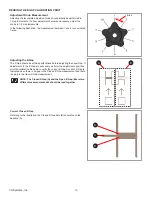
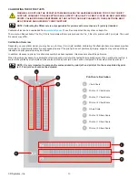
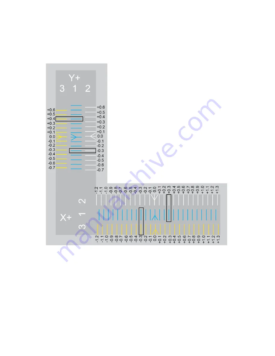
In the print scale illustration, the X+ scale (left-to-right) contains three (3) rows of printed lines . Each line represents a print jet . The
prints are numbered 1, 2 and 3 for each of the three print jets . Print jet 1 always prints the middle scale so the scales of print jets 2 and
3 can be easily compared to it . Print jet 2 prints above print jet 1 and print jet 3 prints below print jet 1 . For printers with only two (2) print
jets, the scale below the print jet 1 scale will not be printed .
The lines on the calibration print represent an offset of 0 .1 mm and should be measured from the printed arrows in the center of the
scales .
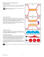
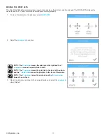
Reading the Offset Jets Scale
Note the white arrow printed from print jet 2 and compare it to the positioning of the blue arrow printed by print jet 1 . Note that the white
arrow is slightly left of the blue arrow meaning that print jet 2 is misaligned . Print jet 2 must be moved in a positive direction (right) to
align with print jet 1 .
Compare the printed lines of print jet 1 and 2 to the right of the arrows and find the printed lines that are properly aligned. In this
illustration, the lines at +0 .3 are aligned . This means that the offset must be corrected by increasing the offset by .3 mm .
When comparing the arrow printed by print jet 3 to the arrow printed by print jet 1, notice it is positioned slightly to the right . This means
it must be adjusted in a negative (left) direction. Compare the lines of print jet 1 and 3 to the left of the center arrows and find the
printed lines that are properly aligned, In this illustration, the lines at -0 .3 are aligned . This means that the offset must be corrected by
decreasing the offset by .3 mm .


