


p/n xx-xxxxxx
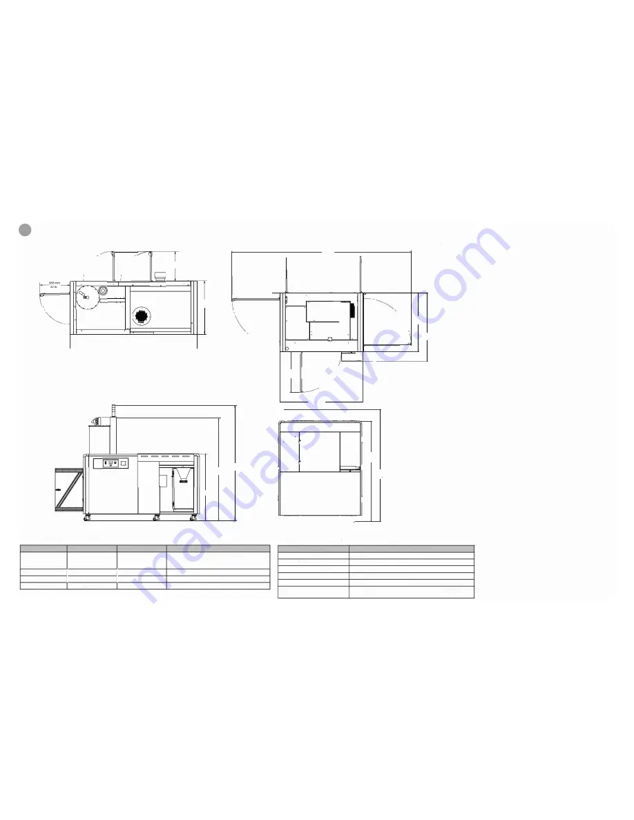
PROX SLS 6100
3754 mm
148in.
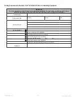
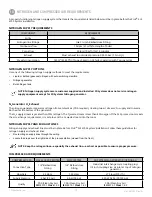
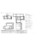
ATMOSPHERE REQUIREMENTS
(
(
560mm
22 in.
I
n�, /�
779mm
\
(
31 in.
L
·1
i
ATMOSPHERE VARIABLES
REQUIREMENTS
Room temp. controls
Heating & air conditioning installed
A/C not blowing on top of process station
□·
2382 mm
□·
□·
-----------
-------------
94in.
1548mm.
39 in.
1364 mm
54 in.
�
2364 mm
2108 mm
93 in.
83 in.
NOTE: WEIGHT OF SINGLE MQC (497.39 kg/1097 lbs.)
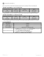
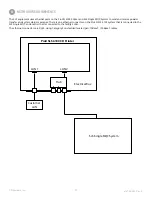
COMPRESSED AIR REQUIREMENTS
COMPRESSED AIR
ProX 6100 3D PRINTER
MQC SYSTEM
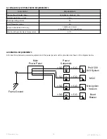
3D SYSTEMS N
2
GENERATOR (OPTIONAL)
Industrial inter,change male cou;pliing 1Plug:
Connection Type
1/4" Barbed Hose Fitting 1/4" Barbed Hose Fitting
1/4 intll coupling size, air inlet at top of nitrogen
generator
flow Rate
I
35slpm
I
130 slpm
270 1pm (572 cfh)
Supply Pressure
I
6 bar (90 psi)
1
6 bar (90 psi)
620-690 kPa (90-100 psi)
Qualit
y
CDA (Clean Dry Air)
GOA
CDA
-
.0.
I
�
":'
---
■
---
---
---
---
---
-
---
---
-
·o
Q
-·
•
-
-
-
-
-
-
•
•
-
--
•
CJt
I
I
857mm
/
34 in.
/
1743mm
69
In.
�
�
□
.
rn
D
•
.
::,;.!:
:
c::::::::J '"
�
.
.
!!
\
1222 mm
48 in.
1435
mm
56in
,___ 1005 mm/40 in.
�
� 213m�/ 8in .
i
2109mm
83 in.
i
2353
mm
93in
i
Temperature
Non-condensing
Room air changes
Heat dissipation
Atmospheric corrosives
Operating range: (16 to 32)
°
C; (60 to 90)
°
F
Stability:± 2
°
C (± 5
°
F)
No higher than 70%
4 per hour minimum
Maximum: SkW (17,000 BTU/hr)
Average: 3.2 kW (11,000 BTU/hr)
None; Clean Dry Air (CDA) is required
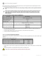
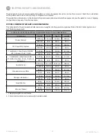
ELECTRICAL REQUIREMENTS
COMPONENT
Process station input voltage
Normal operating current
Peak operating current
On/Off fuse rating
Power cable (for 3-phase power)
Power cable circuit breaker wiring
REQUIREMENTS
208 VAC, 1 0kVA, 50/60 Hz, 3PH
10 to 21 A
25 A
35 A
(3 Delta Con P.E. connection)
phase 1 to L 1
phase 2 to L2
phase 3 to L3
The 3-phase power cable and cable gland (cord grip) are customer-supplied
and installed. The cable feeds through the access port on the top of the printer.
Connect the power cable ground wire to the ground bus bar in the printer's
power disconnect box.
*Verify with yourlocal building codes that this confoguration meets local requirements .
SLS SINGLE MQC SYSTEM POWER REQUIREMENTS
If the facility does not have 208 VAC, 3-phase, 50/60 Hz, 10 kVA power,
a customer-supplied step-up or step-down transformer is required.
3D Systems stocks the following transformers:
COMPONENT
Input voltage (Single Phase)
Normal operating current
Peak operating current
On/Off breaker rating
Power Cable IEC320-C10 Plug
Max. Room Ambient Temp.
REQUIREMENTS
208-230VAC, 50/60Hz, 1 PH
1.6 A
4A
SA
16AWG (01.29mm)
(2 Con P.E. Connection)
27
°
C
*Verify with yourlocal building codes that this confoguration meets local requirements.
NOTE: WEIGHT OF PROJET SLS 6100 (1469kg / 3239 lbs.)
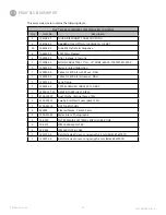
NITROG E
N
I
SUPPLY REQUIREMENTS
COMPONENT
REQUIREMENT
Purity
99%
Nitrogen line fitting,s
llnlet ¼ inch Barbed Hose F
i
tti
ng
1
Continuous flow
10 slpm (21 scfh) for
l
ength
,
of build
Purgelilow
50 1pm (106 cfh) for 15 minutes
Exhaust
Must exhaust to outside at pressure 0.0025 bar (1.0 in Hp)
Weeldy consumpliion
140 rn3 (4944 ffl) of IN
2
gas based on 24 h/day qperation with
7 1PUrge cycles
15
ProX 6100 SLS 3D PRINTER FACILITY REQUIREMENTS POSTER
Rev_B


