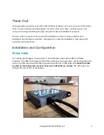
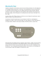
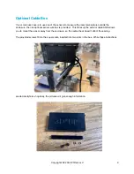
background image

Mounting the Case 

Installation depends on what exactly you want to do with the touchscreen. The first release has 
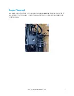
two separate temperature sensors on long wires. The simplest thing is to lay the touchscreen 
on the table for testing purposes and use a cable access port to bring the cables inside the 
enclosure. However, the air quality VOC meter should be close to the top of the enclosure to 
get a good reading.  We’ve had good luck mounting the case near the top of the sides on the 
left or right.  

If you purchase a 3D UPfitters enclosure, it will come pre-cut to place the touchscreen case at 
either the top left or top right near the front.

If you’d like to mount the touchscreen on your enclosure, the STL for a drill template is 
available at the bottom of the main product page. The holes labeled S1 and S2 will enable you 
to bring the sensor cables into the enclosure hidden behind the case for a cleaner look.

Note that holes will be added to the fan controller in future versions.  While we don’t like having 
to drill holes, this is the least bad of the available solutions.  We will make every e

ort not to 

change the holes' location; future directions force later versions to not be compatible with this 
hole pattern.  If you are squeamish about leaving holes in your enclosure, you’ll probably want 
to wait until later versions are released in the latter half of 2022. 

Copyright 2022 3D UPfitters LLC

4

Summary of Contents for Temp Sensor

Page 1: ...Temp Sensor VOC Sensor Installation Manual 2 6 August 2022 Copyright 2022 3D UP fi tters LLC 1 ...

Page 2: ...We forgot to put something on this page Copyright 2022 3D UP fi tters LLC 2 ...

Page 3: ...ible We depend on customer feedback to help shape this product s future directions Installation and Con fi guration Power Cable Ain t nothing gonna happen til you plug it in The touchscreen comes with a USB C to USB A connector The USB C side plugs into the bottom of the case as shown below We don t provide a wall wart as we highly recommend purchasing power strips with built in USB power It s cru...

Page 4: ...he top left or top right near the front If you d like to mount the touchscreen on your enclosure the STL for a drill template is available at the bottom of the main product page The holes labeled S1 and S2 will enable you to bring the sensor cables into the enclosure hidden behind the case for a cleaner look Note that holes will be added to the fan controller in future versions While we don t like...

Page 5: ... clips are provided to help position the sensors inside the enclosure or you can DIY your solution The VOC sensor is inside the case which can be exposed to air inside the 3D printer enclosure Copyright 2022 3D UP fi tters LLC 5 ...

Page 6: ...emperature values in Farenheight We can add Celcius in the future if people tell us they want it but we kept the initial release simple in case customers wanted us to go in a di ff erent direction To view the historical time for each sensor tap on one of the blue buttons Copyright 2022 3D UP fi tters LLC 6 ...

Page 7: ...ing laser cutting or other air pollutants Why is the fi rst 12 hour calibration necessary The fi rst time your device is powered on it has no preexisting baseline so it must fi nd one Because each sensor has atomic level di ff erences due to the manufacturing processes each has a unique baseline resistance Running the sensor for 12 hours initially allows it to come into contact with ordinarily occ...

Page 8: ...subject and requires a lot of background knowledge and even then is pretty complicated When we were testing the device the readings didn t make sense at fi rst as the values didn t seem to correlate to the 3D printing process and then we discovered the laser exhaust wasn t working correctly The point here is that the 3D printer is only one source of poor indoor air quality so keep that in mind whe...

Page 9: ...rovided This tidies up the exterior cable AND allows you to mount the sensor away from the enclosure so the radiant heat doesn t a ff ect the reading The provided screws fi t into the square nuts inserted into two slots in the box While these instructions are decidedly terse hopefully the pictures will give enough information Copyright 2022 3D UP fi tters LLC 9 ...

Page 10: ...oprint The values for temperature and air quality can optionally be displayed in real time in Octoprint If you want to run Octoprint that s beyond the scope of this manual but there are plenty of online resources on how to hook your 3D printer to Octoprint These instructions will focus on connecting this device to an existing Octoprint installation The fi rst step is con fi guring the device for W...

Page 11: ...he product page and install that You ll need to use the touchscreen to fi nd the URL and then con fi gure the plugin Once you start a print the display will include the values from the two temperature sensors and the VOC sensor Copyright 2022 3D UP fi tters LLC 11 ...

Reviews: