background image

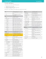
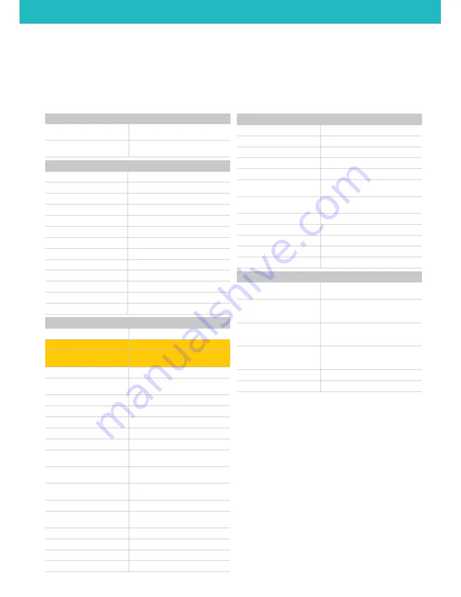
LCD CONTROL UNIT OPERATION

There are three main functions of the LCD Control Unit:

1.  Prepare the printer for printing

2. 

Manual control—both prior-to and during printing 

3.  Starting a print from the SD card

Use the button / knob combination to select and scroll through the screen options.
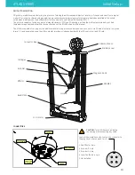
ATLAS SERIES

Operating

PLAY

Opens the PLAY menu

       SD...

List of .gcode files from internal memory 

card

       EXT...

List of .gcode files from external 

memory card

JOG

Opens Move Axis menu

       Back...

Returns to main menu

       Move 10 mm

Opens Move Axis 10 mm menu

              Move X

Moves X axis in increments of 10 mm

              Move Y

Moves Y axis in increments of 10 mm

              Move Z

Moves Z axis in increments of 10 mm

       Move 1 mm

Opens Move Axis 1 mm menu

              Move X

Moves X axis in increments of 1 mm

              Move Y

Moves Y axis in increments of 1 mm

              Move Z

Moves Z axis in increments of 1 mm

       Move 0.1 mm

Opens Move Axis 0.1 mm menu

              Move X

Moves X axis in increments of 0.1 mm

              Move Y

Moves Y axis in increments of 0.1 mm

              Move Z

Moves Z axis in increments of 0.1 mm

PREPARE

Opens prepare menu

      Home all axis

Homes the machine to x0, y0, z0

      Set Home

DO NOT USE  Sets home position

      Set Z0

DO NOT USE  Sets temprally new bed 

height

      Motors Off

Turn off the motors

      Preheat

Heat the hotend to 180°C and the bed 

to 60°C

      Cooldown

Turn off any heating

      Extruder

Opens the Extruder menu

             Extrude 5mm

Extrude 5mm of filament

             Retract 5mm

Retract 5mm of filament

             Settings...

Opens the Extruder Settings menu

                    E steps/mm

Number of steps required for the 

extruder to wmove 1 mm of filament

                    Filament d

Sets the filament diameter ( only for 

volumetric extrusion )

                    Flow Rate

Sets extruder factor/multiplier for all 

extruders—expressed in percentage

                    Accel

Sets the extruder stepper accelleration

                    Retract Le

Sets the retraction lenght ( only for 

volumetric extrusion )

Set Temperatures

Opens the Temperatures menu

       Back...

Returns to previous screen

       Hotend

Sets the hotend temperature

       Bed

Sets the bed temperature

CUSTOM

Opens custom  menu

       Layer Fan ON

Turn on the layer fans

       Layer Fan OFF

Turn off the layer fans

       Go to load Position

Lower the extruder for easy access

       SD Suspend

Pause the current print

       SD Resume

Resume the current print

       E0 Extrude 10mm

Extrude 10mm of filament using  

extruder 0

       E0 Retract 10mm

Retract 10mm of filament using 

extruder 0

       Calibrate CENTER

Move the nozzle to the center of the bed

       Calibrate ALPHA

Move the nozzle near the alpha tower

       Calibrate BETA 

Move the nozzle near the beta tower

       Calibrate GAMMA

Move the nozzle near the gamma tower

        Save Z0

Save the current position as Z0

CONFIGURE

Opens configure menu

        Accelleration

Sets the global accelleration for XYZ 

moovments

        X Steps / mm

Number of steps required for the 

stepper motor to move 1 mm in the X 

direction

        Y Steps / mm

Number of steps required for the 

stepper motor to move 1 mm in the Y 

direction

       Z Steps / mm

Number of steps required for the 

stepper motor to move 1 mm in the Z 

direction

        Z Home Ofs

Sets the offset

       Contrast

Sets the LCD contrast

20

Summary of Contents for ATLAS 4030

Page 1: ...USER MANUAL ATLAS 4030 ATLAS 4070 This guide will take you through the steps to set up and operate your 3DBNZ ATLAS 3D printer Version 1 3 Revision A ...

Page 2: ...thin the Warranty Period 3DBNZ or an authorized service company will correct in a reasonable commercial time the claims related with the non conforming Product according to the following clauses WARRANTY PERIOD The Warranty Period starts when the Product is first delivered to the end user The Warranty period lasts twelve 12 months Both the parts that suffer wear and tear due to the normal operatio...

Page 3: ...ng the Nozzle 19 Printing Via SD Card 19 Printing Via USB Connection with Computer 19 LCD Control Unit Operation 20 SOURCE FILES 21 Typical Work Flow 21 PREPARING FILES FOR USE 22 Converting 3D model to stl 22 Converting stl to gcode 22 Basic slicing parameters 23 Start Gcode 23 End Gcode 23 3D PRINTING MATERIALS 24 Recommended Temperatures 24 Vendors and Manufacturers 24 Storage Recommendations 2...

Page 4: ...ion where the printer is operating should be equipped with working smoke and flame detection The 3DBNZ ATLAS printer melts material during printing Some materials may require ventilation Do not leave the 3DBNZ ATLAS printer unattended while in operation The 3DBNZ ATLAS includes linear actuators that move in multiple directions at variant speeds When in motion they may cause injury Do not place hea...

Page 5: ...ymbol Meaning Location Comments WARNING HOT SURFACE Print nozzle Print bed A hot surface is located in the vicinity do not touch CRUSHING OF HANDS X axis Y axis Z axis When in motion the Altas linear actuators that move in multiple directions at variant speeds may be a pinch hazard low risk due to force limitation ON Rear panel of electrical box Turns the machine on OFF Rear panel of electrical bo...

Page 6: ... C Heated bed max 100 C Hotend cooling 30x30x10 24v fan Internal electronics cooling 80x80x20 24v fan INFORMATIONS Manufacturing technology Fused filament fabrication FFF Printing volume Cylindical 400mm diameter x 300mm height Cylindical 400mm diameter x 700mm height Nozzle size 0 4 mm standard 0 15 0 25 0 3 0 5 0 6 available Layer height 0 05 mm 0 5 mm Repetability XY 0 02mm Z 0 05 Filament diam...

Page 7: ...nter dimensions illustrated below Note Dimensions are not considering the filament spool 1047 77 579 89 641 55 625 78 ATLAS 4030 1447 77 579 89 641 55 625 78 ATLAS 4070 ATLAS SERIES DIMENSIONS ATLAS 4030 ATLAS 4070 7 ...

Page 8: ...urer Take great care not to break or splinter the printing surface which is made of glass CAUTION The unit is heavy Care must be taken to assure safety of machinery and operators Take care if using sharp tools for unpacking A phillips head screw driver is required 1 Unscrew the screws and remove the front panel 2 Carefully remove bracing supporst and or tie downs what are used to secure the produc...

Page 9: ...d able to stand the device weight and to absorb the vibrations If the surface is not flat use the three regulation feet under each tower On the right side of the device is positioned the switch this side should be easy accessible on the lower side of the device there are the air inlets and the fan that provides to the correct cooling of the electronics and the motors Keep the cooling air inlets cl...

Page 10: ...s capable of carrying out the additive manufacturing process under open source controls via 3D model output in the gcode format It can be operated using the USB computer interface or independently with the LCD control unit and SD card Layer Fan Z Probe Extruder 1 Not installed End Effector Extruder 0 Layer Fan Z Probe Extruder 1 Not installed End Effector Extruder 0 CAUTION Turn OFF the machine be...

Page 11: ...repare the printer 1 LCD PANEL INSTALLATION Connect the two ribbon cables to the LCD control unit and install it on the front of the machine Cables are numerated 2 and 3 2 BUILD PLATE Remove the 3 clips that hold the glass in place during shipping and any other styrofoam 3 FILAMENT ROLLER Put the spool rollers on the top of the machine Check if the spool turns freely and make sure is stable and se...

Page 12: ... 1 Hold a piece of opaque material into each sensor The red light should turn off when triggered 2 Using the LCD controls check if the CPU are receiving the signal when triggering each endstop sensor LCD PROBE STATUS Contact 3DBNZ if sensors are nonoperational Do not attempt to operate the printer TESTING THE AXIS 1 Check that nothing blocks the axis mechanisms belts pulleys etc 2 Ask the printer ...

Page 13: ... ATLAS should be discovered where all configuration and firmware related files are stored The disk can also store g codes for printing 4 Important please copy all contents of the SD card drive as soon as you can backup 5 After that you can connect to the machine using a host of your choice which can be for example pronterface http www pronterface com 6 In Pronterface select the correct COM port an...

Page 14: ...glass barely pinching the paper Go down until you can feel slight resistance while sliding the paper for fine adjustment you can select finer jog increments LCD JOG MOVE 1mm MOVE Z 4 Tell the printer how far in Z is the build plate from home position LCD CUSTOM SET Z0 Now the printer will home and store the new height information into Config Override file on the internal memory 5 Move the effector...

Page 15: ...sh the filament by hand into the extruder until you see material flowing from the nozzle The filament must flow consistetly without applyng to much force Adjust temperature so the force needed to push the filamnent in is not too high 6 Turn the knob until the extruder block is fully closed IMPORTANT Do not overtight the knob Depending on filament elasticity you can adjust the tensioner force by tu...

Page 16: ...ic loosening and the part will pop off the print bed Operate the temperature of the print bed through the LCD control unit or with 3D printing software See the Recommended Temperature table CAUTION For the safety of the user use extreme caution when working with heated machinery PREPARE THE PRINT BED Prepare the build area for printing In order for your prints to adhere to the glass it needs to be...

Page 17: ...adhesion 5 Wait the printer to cool down before removing the printed object PRINT YOUR OWN GCODE You can print your Gcodes in 3 different ways 1 Load the Gcode into the internal 2GB memory using the USB cable slow transfer safe to print 2 Load the Gcode on a FAT 32 formatted SD insert the SD into the LCD fast transfer safe to print 3 Stream the Gcode trough the USB connection using a host software...

Page 18: ...º C use a crescent wrench and 7 mm wrench to remove the nozzle Use the crescent wrench to hold the base steady and not able to rotate Use caution nozzle is hot 5 Once nozzle is removed select the replacement nozzle Nozzle size can be determined by inspecting stamped numbers along the side of the nozzle 6 Once new nozzle has been selected hand thread it into the extruder 7 Then use the wrench and c...

Page 19: ...ant gloves Use appropriate tools for all cleaning and maintenance ATLAS SERIES Operating PRINTING VIA SD CARD The ATLAS can be operated independently with the LCD Control Unit and an SD Card Select PLAY on the LCD Control Unit then choose the gcode file you wish to print PRINTING VIA USB CONNECTION WITH COMPUTER The ATLAS can be operated through the 3D printing software s Manual or Machine Control...

Page 20: ...ilament Settings Opens the Extruder Settings menu E steps mm Number of steps required for the extruder to wmove 1 mm of filament Filament d Sets the filament diameter only for volumetric extrusion Flow Rate Sets extruder factor multiplier for all extruders expressed in percentage Accel Sets the extruder stepper accelleration Retract Le Sets the retraction lenght only for volumetric extrusion Set T...

Page 21: ...at The stl or obj file is loaded into 3D printing software where 3D print parameters are applied Once print parameters are applied and the file is processed commonly called slicing the file is output as a gcode for the printer Models designed for 3D printing can be found online at sites such as GrabCAD 3D Marvels 3D Via Google 3D Warehouse Turbosquid and Thingiverse TYPICAL WORK FLOW Create or dow...

Page 22: ...nt multiple objects in one print 2 Arrange the object s on the print bed and orient appropriately for FFF 3D printing see Orienting the Part for Success on page 25 in the Printing Tips section of this manual 3 Apply process slice settings including Layer height Number of outside perimeters vertical shells Number of solid top and bottom layers Percentage of infill Temperature Speed Z hop 4 Select P...

Page 23: ...ines 5 Retraction Amount 2 mm Retraction Vertical Lift Z hop 1 2 mm Retraction Speed 7200 Outline Overlap Percentage 40 Infill Percentage 30 Infill Extrusion Width Percentage 105 Speed 3000 Rapid Speed 6000 Acceleration 2000 START GCODE make sure your slicing software has the following commands in the start routine G28 HOME G92 E0 reset extruder lenght G0 Z20 F6000 approach the build plate END GCO...

Page 24: ...is is a guide to temperatures for various materials such as PLA ABS HIPS PVA and many more Simply click on the link for the material you are interested in and you will see information such as temperature requirements and speed recommendations for that material STORAGE RECOMMENDATIONS Store filament in a cool place Keep temperatures below 122 F 50 C Keep material in sealed container or bag with moi...

Page 25: ...ments as needed If your extruder is not hot enough the filament may not adhere to the print bed If your extruder is not hot enough the filament may not adhere from layer to layer If your extruder is too hot the filament may warp or you may see an unwanted variance in layer width PRINT BED TEMPERATURE The print bed on the ATLAS printer is heated to provide better adhesion of your printed parts Each...

Page 26: ...o the recommended temperature base upon the material being used If adhesion problems persist Increase bed temperature to 80 85º C Increase the nozzle temperature by 10 20º C for the first 1 3 layers to aid in adhesion Decrease the printing speed by 30 for the first layer Increase the flow rate by 5 10 for the first layer Print a test print to ensure good first layer adhesion Gap Too Large Gap Too ...

Page 27: ...J to set probe_radius K to keep current endstop trim settings In Zgrid module it starts the grid probing G32 G32 R G32 E G32 EK G32 I0 02 G28 Home The given axis or if no axis specified home all axis at the same time edge G28 G53 G59 3 use workspace coordinates http linuxcnc org docs html gcode coordinates html and http linuxcnc org docs html gcode g code html gcode g54 g59 3 G54 G90 Absolute mode...

Page 28: ...sabled until G32 is run again Specify X and Y values to change grid size M370 M370 X9 Y11 M371 Z grid strategy moves the head to the next calibration position without saving for manual calibration M371 M372 Z grid strategy move the head to the next calibration position after saving the current probe point to memory manual calbration M372 M373 Z grid strategy completes calibration and enables the Z...

Page 29: ... this period has expired all sales with be considered to be final Not used is understood to mean products that have never been assembled switched on programmed or altered in any other way TERMS AND CONDITIONS OF SERVICE The information in this manual is subject to change at any time without notice and is provided solely for informational purposes 3DBNZ reserves the right to change or modify the ma...

Page 30: ... sharp or cutting elements bending or compressing parts or fall of the product 2 The normal wear and tear occurred for the product normal use including unlimitedly the wear of moving parts control panels or elements interacting with the product operation 3 Malfunctions or damage caused by modifications alterations or repairs by any individual or company not authorized by 3DBNZ The Consumable repla...

Page 31: ...sts if needed 4 3DBNZ or the authorized service company depending on which handles the claim bears the repair parts replacement or Product substitution costs 5 All damaged defective or replaced parts or Products become the property of 3DBNZ or the authorized service company EXCLUSIONS This Warranty does not cover 1 Physical damage caused by an inappropriate transport not using the official packagi...

Page 32: ...p 32 Thank you print responsibly Contact info 3dbnz com www 3dbnz com ...

Reviews: