

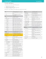


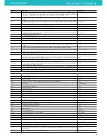
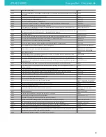


G-Code
Description
Example
G0
Move to the given coordinates. To the contrary of G1, if there is a tool it will most of the time be off during this
kind of move. This is a "go to" move rather than a "do while going to" move. The F parameter defines speed and is
remembered by subsequent commands ( specified in millimetres/minute ) (command is modal)
G0 X10 Y-5 F100
G1
Move to the given coordinates, see above for difference with G0. Takes the same F parameter as G0. (command is
modal)
G1 X20 Y-2.3 F200
G2
Clockwise circular motion : go to point with coordinates XYZ while rotating around point with relative coordinates
IJ (command is not modal)
G2 X10 J5
G3
Counter-clockwise motion : see above (command is not modal)
G3 Y5 X10 I2
G4
Dwell S<seconds> or P<milliseconds>
G4 P1000
G10
Do firmware extruder retract
G10
G10 L2 G10 L20
set workspace coordinates http://linuxcnc.org/docs/html/gcode/coordinates.html and http://linuxcnc.org/docs/
html/gcode/g-code.html#gcode:g10-l2
G10 L2 P1 X0
G11
Do firmware extruder un-retract
G11
G17
Select XYZ plane (command is modal)
G17
G18
Select XZY plane (command is modal)
G18
G19
Select YZX plane (command is modal)
G19
G20
Inch mode : passed coordinates will be considered as Inches, so internally translated to millimeters (command is
modal)
G20
G21
Millimeter mode ( default ) : passed coordinates will be considered as millimeters (command is modal)
G21
G30
Simple Z probe at current XY, reports distance moved down until probe triggers. optional F parameter defines the
speed of probing, zprobe.slow_feedrate is used when not supplied
G30 - G30 F100
G31
Report current Z probe status
G31
G32
Uses Z probe to calibrate delta endstops and arm radius, use R parameter to select only arm radius calibration
and E to select only endstop calibration. I to set target precision, J to set probe_radius, K to keep current endstop
trim settings. In Zgrid module, it starts the grid probing
G32 - G32 R - G32 E - G32 EK - G32
I0.02
G28
Home The given axis, or if no axis specified home all axis at the same time (edge)
G28
G53-G59.3
use workspace coordinates http://linuxcnc.org/docs/html/gcode/coordinates.html and http://linuxcnc.org/docs/
html/gcode/g-code.html#gcode:g54-g59.3
G54
G90
Absolute mode ( default ) : passed coordinates will be considered absolute ( relative to 0.0.0 ) (command is modal)
G90
G91
Relative mode : passed coordinates will be considered relative to the current point (command is modal)
G91
G92
Set current position to specified coordinates
G92 X0 Y0 Z0
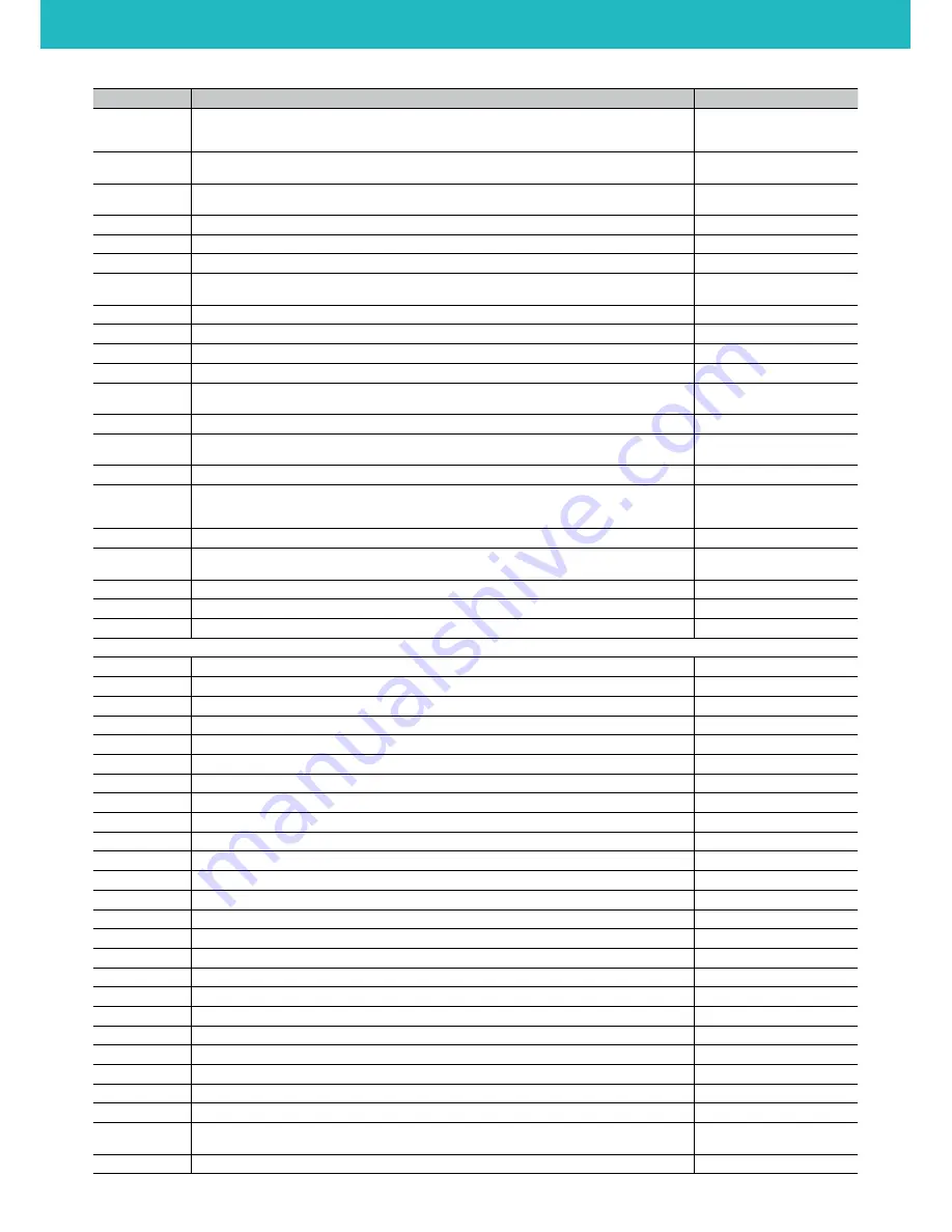
M-Code
M17
Enable stepper motors
M17
M18
Disable stepper motors
M18
M20
List SD card files
M20
M21
Initialize the SD card. This does nothing in Smoothie but is kept for compatibility
M21
M23
Select a file
M23 file.gcode
M24
Start or resume SD card print
M24
M25
Pause SD card print
M25
M26
Abort a SD card print
M26
M27
Report print progress
M27
M28
Begin write to SD card. Use M29 to indicate end of file.
M28 file.gcode
M29
End write to SD card. Used to end file write started with M28.
M29
M30
Delete a file on the SD card
M30 file.gcode
M32
Select a file, and start playing it
M32 file.gcode
M82
Set absolute mode for extruder only
M82
M83
Set relative mode for extruder only
M83
M84
Disable steppers
M84
M92
Set axis steps per mm
M92 E200
M104
Set Extruder Temperature - S<temperature>
M104 S190
M105
Read current temp
M105
M106
Turn fan ON
M106
M107
Turn fan OFF
M107
M109
Set Extruder Temperature and Wait - S<temperature>
M109 S190
M110
Set current line number -N<line number>
M110 N123
M112
Halt all operations, turn off heaters, go into Halt state
M114
Show current position of all axes, XYZ will be the last requested position, whereas ABC is actual current position of
the actuators
M114
M117
Display message on LCD, blank message will clear it
M117 hello world or M117
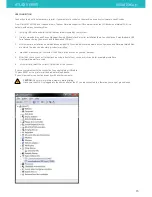
ATLAS SERIES
Supported Commands
27


