32 | 3DGence INDUSTRY F340
XY Calibration
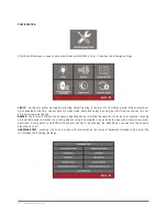
– calibrating dimensional compatibility in X and Y axes. The process is detailed in the MAINTENANCE
chapter, section 3.
Heat Bed Scan
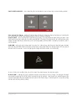
– starts the procedure of automatic printer bed calibration. The process takes about 15 minutes. During
this process the head is positioned in succession over 200 measurement points. Load cells installed in the dual-head mod-
ule detect the surface of the printer bed while its readings are saved in the form of calibration matrix in device memory.
Printing Module Calibration
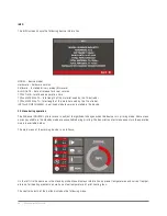
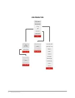
– menu for the Dual-head module. The options available in the menu are as follows:
X Offset
– difference in extruder 1 nozzle position in relation to 0 in axis X. A correct value eliminates the offset that may
occur between nozzles tips set in working positions An improper setting is presented in the figure 23:
CAUTION: the Offset X,Y and Z values refer always the T1 head position to absolute T0 head position.
Y Offset
– similarly to X Offset, Y Offset defines the position difference for extruder 1 nozzle in relation to 0 nozzle in Y
axis at the working position.
Z Offset
– similarly to X Offset, Z Offset defines the position difference for extruder 1 nozzle in relation to 0 nozzle in Z
axis at the working position. A proper calibration for deviations in Z axis are of key importance for supporting structures
to perform their functions properly. The calibration of differences in nozzle height can be performed by using the tool
described below, being the second item of PRINTING MODULE CALIBRATION menu.
Fig. 23. A diagram showing the differences in head positions in working position (offset).
Hotend T0
Hotend T1
Offset
Summary of Contents for INDUSTRY F340
Page 1: ...USER MANUAL 3DGence INDUSTRY F340 ...
Page 2: ...2 3DGence INDUSTRY F340 ...
Page 39: ...3DGence INDUSTRY F340 39 version 1 0 07 2017 ...
Page 43: ...3DGence INDUSTRY F340 43 version 1 0 07 2017 ...
Page 86: ...86 3DGence INDUSTRY F340 ...
Page 87: ......


