background image

page

 1

... print your plane  | www.

3DLabPrint

.com

Fully 3d printable

North American B-25J Mitchell

12:1 ~ wingspan 

1.72m/68in

User Guide

rev. 2019/12

Summary of Contents for North American B-25J Mitchell

Page 1: ...page 1 print your plane www 3DLabPrint com Fully 3d printable North American B 25J Mitchell 12 1 wingspan 1 72m 68in User Guide rev 2019 12 ...

Page 2: ...comparable or even supperior to classic build model airplane This is not a dream now you can print this HI TECH at home Simply download and print the whole plane or spare parts anytime you need just for a cost of filament only about 40 Extensive hi tech 3d structural reinforcement making the model very rigid while maintaining a lightweight airframe and exact airfoil even it s just a plastic This p...

Page 3: ... in from LE Airfoil 3DLabPrint semi 04 Weight of printed parts w o wheels 1980 g 72 7 oz Takeoff weight 4s 5000mAh Li Pol 3600 g 160 5 oz Max takeoff weight 4200 g 194 oz Never exceed speed Vne 120 km h 93 mph Design max maneuvering speed Va 75 km h 46 mph Stall speed Vs 32 km h 17mph Performance measurement Max speed VH level flight 110 km h 75 6kn 87 0mph Rate of climb 21 m s 6 500 ft min Flight...

Page 4: ...blems These improvements included fitting 1 600 hp 1 193 kW Wright R 2600 Twin Cyclone radial engines in March 1939 which solved the lack of power In March 1939 North American delivered the substantially redesigned and improved NA 40 as NA 40B to the United States Army Air Corps for evaluation It was in competition with other manufacturers designs Douglas 7B Stearman X 100 and the Martin Model 167...

Page 5: ...kerware slicers 2 Factory files for Simplify3D slicer With all our settings these Factory files include all you need Note we use PRUSA i3 ORIGINAL printers so you may need to adjust the basic printing parameters to match your printer or use it as a starting point for you Please look at Simplify3D 3 Step By Step PDF VIDEO userguides Please use this user guide along with the Printing Guide where you...

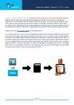
Page 6: ...gonna work with your printer 5 Prepared settings for CURA and MatterControl slicers If you can t use Simplify3D for any reason we provide our basic configuration files for free slicers CURA and MatterControl Use these as a start point and amend as needed 6 Scale markings and masking patern in PDF Print this PDF on self adhesive foil cut it and put it on the model according to your preferences Mart...

Page 7: ...page 7 print your plane www 3DLabPrint com Lenght 1360 mm 53 6 inch Wing area 43 dm2 4 7 sq ft CoG is 83mm 3 27 in from LE Centre of Gravity ...

Page 8: ...page 8 print your plane www 3DLabPrint com Wing span 1720mm 68 inch ...

Page 9: ... part 1 Create account download You ll get the download link for all zipped files to your email or log in to your account and download directly from our website If you don t receive the link right on checkout please contact us on support 3dlabprint com mentioning the order number WC XXXXX on PayPal receipt 2 Gcodes preparing option A Gcodes If your printer is i3 compatible you can directly use the...

Page 10: ... the use of our settings If you still encounter any dificulties please proceed to the next option option C Simplify3D manual setting watch and learn Use our VIDEOGUIDE and how to to find explanation of proper settings This is great option to learn a lot about Simplify3D and become a 3D expert Of course you spend a lot of time and the youtube pause button will become your friend For simplification ...

Page 11: ...oper multiplier settings Please check the Cura setup guide in the Help section As a starting point you can use our predefined CURA profile Always adapt the settings for your printer change build volume filament diameter etc according to your printer Please be aware some parts require different settings of perimeters top bottom layers and infill For some thick part you ll need to use support struct...

Page 12: ...suitable for this Scaling the model will lead to unusable result Note ninja flex or simmilar fillaments can stick very hard to PEI based surfaces be careful You will need PLA filament good quality we need good layer bonding Strong hair spray or your favorite adhesive bed surface disregard with PEI or similar bed surface Mk2 3 Razor blade AND please watch the VideoGuides video printing guide 3 Nort...

Page 13: ...s if needed Heated bed is very recommended use 50 56 Celsius to print without warping ends Any standard quality PLA is suitable to print our planes but the result depends on combina tion of PLA vs Extruder vs HotEnd Some colors and brands of filament has lower layer adhesion please do experiment with it There are a lot of 3dprinters on the market most of them are OK for printing our aircraft speci...

Page 14: ...r CA Glue or similar gas presurized works better Soldering Iron or any hot tool to cut holes 1 75 2mm rod axle for flap hinge we use fillament or toothpick sound as a option ESS AIR Engine Sound System cable extension Proceed the way shown in videoguide See video guide 4 1 flap2 L 19g 0 67oz flap1 L 22g 0 78oz wing L 2 82g 2 9oz wing L 4 42g 1 48oz motor mount 11g 0 39oz eng gondola1 68g 2 4oz eng...

Page 15: ...ration speakers use a hot tool to cut the hole for speaker cable the smaller area marked red in the picture Stick the speaker to botom of the pod use IP alcohol to degrease contact surface Proceed the way shown in videoguide See video guide 4 1 Apply CA glue to the contact surfaces marked red in the picture and assemble together then apply the activator proceed this way with gondola parts and glue...

Page 16: ...rocedure submerge in boiling water for more than 30 minutes pla is then much more heat resistant Because PLA shrinks when annealed about 2 it is good idea to use motor_mount_annealing compensated for this effect or you can adjust the scaling exactly for your PLA brand in Simplify3D or any other slicer Continue with R and L motor mount note for proper function there is angle compensation for propel...

Page 17: ...t the parts together apply glue marked red in the picture and assemble together engine gondola and wing1 parts Use any hot tool to cut out the hole marked red in the picture for main landing gear wheel Now first part of wing and engine gondola is ready ...

Page 18: ...rint com Proceed with next step Now glue outer wing parts together please don t glue the last wingtip part at this moment Apply CA glue to the contact surfaces marked red in the picture and assemble them together then apply the activator ...

Page 19: ...om Now you can slide aileron to the main wing hinges Apply CA glue to the contact surfaces marked red in the picture and align the parts together then apply the activator Use any hot tool and remove the hinge support marked red in the picture ...

Page 20: ...ue to the contact surface of the flaps parts marked red in the picture Apply CA glue to the contact surface of the part marked red in the picture and insert it to the main wing part Make sure the aileron axle is in the right position and not contaminated with CA glue then apply activator ...

Page 21: ...TE don t glue the engine gondola and outer wing together For flap hinges you can use any 1 75 2mm rod we use piece of fillament or toothpick Apply CA glue to the contact surfaces marked red in the picture and insert flap with hinge then apply the activator and operate the flaps till CA glue is completely cured ...

Page 22: ... is better Soldering Iron or any hot tool 2x 3 5 20mm max 4 30mm self tapping screw Proceed the way shown in videoguide See video guide 4 2 F8 50g 1 76oz F7 61g 2 15oz F6 57g 2 01oz F5 82g 2 89oz F4 110g 3 88oz F3 74g 2 61oz F2 90g 3 2oz batt cover 32g 1 13oz F1 9g 0 32oz F9 35g 1 23oz F_cover_bomb 43g 1 52oz top_gun 21g 0 74oz The weight of parts can vary 8 due to diff PLA color or brand ...

Page 23: ...fe to clean the shape of printed parts but mostly this is not necessary Glue in the sure bonds small triangle parts to the slots in fuselage F2 F3 parts Go ahead and glue fuselage together parts as shown on the picture below Now you can proceed with next fuselage parts there is a bit different coupling system bayonet coupling proceed the same way as with the wing assembly ...

Page 24: ...d with glueing fuselage bomb cover parts together and use two self tapping screws to mount it to the fuselage Now main fuselage is completed Now battery cover cut out both print supports marked red in the picture Glue both top_gun turret parts together ...

Page 25: ...s part with gondolas into the fuselage Proceed with the opposite side The result should look like the picture below Test fit the parts then apply CA glue to the contact surface on the wing marked red in the picture and insert to the fuselage finally apply the activator ...

Page 26: ... guide 4 3 You will need CA Glue medium or similar medium viscosity CA glue Activator for CA Glue or similar but gas presurized aerosol is better 8x 3 5 20mm self tapping screws 12 750mm carbon tube 1 5mm carbon rod or steel wire rudder hinges H stabilizer L 52g 1 83oz elevator L 29g 1 02oz V stabilizer 29g 1 02oz rudder 21g 0 74oz The weight of parts can vary 8 due to diff PLA color or brand ...

Page 27: ...zer parts Go ahead and complete both stabilizer sides and glue them together now side by side Apply CA glue to the contact surfaces marked red in the picture and insert them together then apply the activator Proceed the way shown in videoguide pictures will help you See video guide 4 3 ...

Page 28: ...ane www 3DLabPrint com Well the horizontal stabilizer is completed assemble the elevator and fit them to the mounts Glue both parts of the vertical stabilizer together side by side Lets proceed with the vertical stabilizers ...

Page 29: ... 3DLabPrint com Now you can slide this assembly of tail parts in to the fuselage For rudder hinge use a 1 2 1 5 mm wire or carbon rod Finally use two self tapping screws to mount it to the horizontal stabilizer Assemble the rudder ...

Page 30: ...page 30 print your plane www 3DLabPrint com And use two self tapping screws to secure it Insert carbon tube 12 750mm into the fuselage ...

Page 31: ...page 31 print your plane www 3DLabPrint com Slide the outer wings to the slots in the engine gondola parts And again use self tapping screw to secure the outer wing to the gondola ...

Page 32: ...page 32 print your plane www 3DLabPrint com Finally attach the engine cowling just snap it on the engine gondola Wow the whole airframe is finished ...

Page 33: ...ilable on every todays RC transmitter and will help reducing the need to compensate manually during final approach The last servo is only eye candy and should be used to rotate the top guner turret Note in case you want to use all the servos and rectractable LG you might want NOT to use servo extension leads but solder the wires directly It makes running the cables through the tunnels easier See v...

Page 34: ... wire then insert it in to the aileron flap arm hole then use some gauge or just pen and mark exactly position of servo arm to wire Cut the wire and make another Z bend Release servo arm and slide the Z bend wire in and put the servo arm on the servo again secure with included self tapping screw Remember you must slide all servo cables in to the servo cable tunnels The servo cable extension must r...

Page 35: ...l wire in to elevator bowden Center servo to its neutral position use your RC system or servo tester Attach the prepared servo arms Remember that you must slide all the servo cables in to the servo cable tunnel and the servo cable extension must reach the battery receiver comparment in the nose of the fuselage ...

Page 36: ... then insert it in to the rudder arm hole then use some gauge or just pen and mark the position of the servo arm Cut the wire and make Z bend Release servo and slide the Z bend wire in and put the servo again in rudder servo slot in vertical stabilizer Remember that you must slide all servo cables in to the servo cable tunnel and the servo cable extension must reach the battery receiver comparment...

Page 37: ...page 37 print your plane www 3DLabPrint com Or just use your favorite servo linkage some Ideas bellow ...

Page 38: ...f LG failure and crash we knof this is the most common reason of the LG failure not the QC problem Check LG function after each landing Proceed the way shown in videoguide PDF See video guide 6 1 You will need Light Foam Main Wheel or any similar 85 90mm Nose wheel or any similar 45 60mm Servoless Retract 44mm x 41mm Mount or similar Servoless Steerable Nose Retract 44mm x 41mm Mount or similar 3x...

Page 39: ...pictures will help you See video guide 6 1 Insert LG unit then use any hot wire marked red in the picture and make hole for four self tapping screws Shape the 5mm steel rod using vice you can add fire and hammer according to the 3D printed template cut the ends slide in main wheel and secure it with Wheel Stop Set Colar and threadlocker Loctite ...

Page 40: ...h self tapping screws again Remember that you must slide all servo cables in to the servo cable tunnel and the servo cable extension must reach the battery receiver comparment in the nose of the fuselage Nose LG gear is similar moreover you need cut out print support marked red in the picture use any hot tool Proceed the same way as with main LG but here is the difference Don t remove the 5mm LG p...

Page 41: ...3DLabPrint com Now add steering servo and linkage solder the pushrod into the clevis Insert the completed nose LG into the slot and secure with self tapping screws again This pictures shows the way that steerable nose LG gear works ...

Page 42: ... characteristic will suffer from aerodynamic drag will be not so smooth and stable You will need Light Foam Main Wheel or any similar 85 90mm Nose wheel or any similar 45 60mm Landing Gear Wheel Stop Set Collar 9x5 1mm or similar 5 mm wire rod for LG leg 18x 3 5 4 30mm self tapping screw Dremell or any steel handsaw Table Vice and Hammer Yeah Torch or lighter ...

Page 43: ...and make hole for four self tapping screws Secure the retract unit using all four self tapping screws Shape the 5mm steel rod using vice you can add fire and hammer according to the 3D printed template for L R main LG and nose LG cut the ends slide in main wheel and secure it with Wheel Stop Set Colar and threadlocker Loctite This section pictures shows the way that fixed LG gear works we have som...

Page 44: ...page 44 print your plane www 3DLabPrint com Insert the completed LG units into the slots and secure with self tapping screws ...

Page 45: ...in this case interupt the red wire from your second ESC servo connector See video guide 8 1 You will need soldering airon etc shrink tube servo cable 3 5mm connectors velcro 8x 3 5 30 self tapping screw Motor 2x 3542 1000KV approx 130g ESC 2x 40A with UBEC 5 5V 4A or better Battery 5000mAh 4S or bigger 600 800g XT 90 1in2 paralel adaptor 12AWG cable for both ESC Propeller 2x two blade 11 x4 5 idea...

Page 46: ...ls Make sure the battery is placed properly and secured in position If battery moves during the flight it can shift the center of gravity backwards and the aircraft becomes uncontrollable See video guide 9 1 You will need your own Rx Tx system 5 14channel see 5 servo chapter 2 5x servo Y cable adhesive velcro strip for Li Pol battery ESC and Receiver battery strap and zip 35 short landing 13 eleva...

Page 47: ... Rudder LG and Elevator linkage before each flight use Loctite when suitable this is not a Toy IMPORTANT retraction of the landing gear must pass smoothly without any contact with the fuselage the landing gear mainly wheels must NOT touch in any case or there is a risk of LG failure and crash we know this is the most common reason of the LG failure not the QC problem Check LG function after each l...

Reviews: