


3
LOWER FRAME AND COMPONENTS
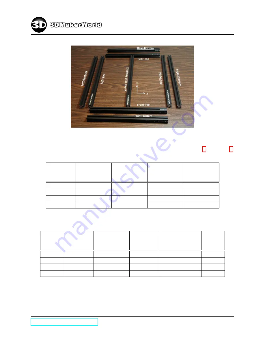
Figure 3.3: Laying out aluminum extrusions of the lower frame
–
Insert M5 T-nuts into slots of aluminum extrusions per list in Table 1 and Table 2.
Four Sides
Front-Top
Aluminum
Extrusion
Front-Bottom
Aluminum
Extrusion
Rear-Top
Aluminum
Extrusion
Rear-Bottom
Aluminum
Extrusion
Top
2
0
3
0
Front
6
6
0
2
Rear
2
1
9
8
Bottom
0
0
0
3
Table 1: Number of M5 T-nuts in slots of X-axis aluminum extrusions on the lower frame
Four
Sides
Left-Top
Aluminum
Extrusion
Left-Bottom
Aluminum
Extrusion
Right-Top
Aluminum
Extrusion
Right-Bottom
Aluminum
Extrusion
Y-Axis
Rail
Support
Top
5
0
8
0
4
Left
4
2
0
3
1
Right
0
0
6
2
1
Bottom
0
6
0
4
0
Table 2: Number of M5 T-nuts in slots of Y-axis aluminum extrusions on the lower frame
•
Assemble aluminum extrusions
25
Summary of Contents for Artifex 2
Page 7: ...1 INTRODUCTION Figure 1 6 The technical specifications of Artifex 2 http 3dmakerworld com 8 ...
Page 16: ...2 PACKING LIST 100 101 102 104 105 106 107 108 109 110 111 112 http 3dmakerworld com 17 ...
Page 17: ...2 PACKING LIST 113 114 115 116 118 119 200 202 203 204 205 207 http 3dmakerworld com 18 ...
Page 18: ...2 PACKING LIST 208 209 209R 210 211 215 216 227 220 221 222 223 http 3dmakerworld com 19 ...
Page 19: ...2 PACKING LIST 224 225 226 300 300D 301 301L 301R 302 304 304D 305 http 3dmakerworld com 20 ...
Page 117: ...8 ARTIFEX 2 DUO Figure 8 4 The assembled Artifex 2 Duo 3D printer http 3dmakerworld com 118 ...


