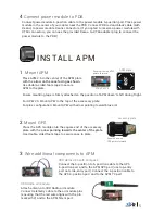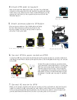
4
1
POWER WIRING
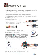
Place power distribution board
2
Solder connectors to electronic speed controllers
The power distribution board (PDB) allocates power to your copter’s motors. Place the PDB
in the center of your copter through the hole in the top plate. Align PDB so the four 8 mm
spacers insert into the four holes in the PDB. Secure with four nylon nuts
Electronic speed controllers (ESCs) regulate how much power is applied to each motor. To
connect the four ESCs to the PDB, you will need to solder the provided Deans connectors to
the ESCs’ black and red wires.
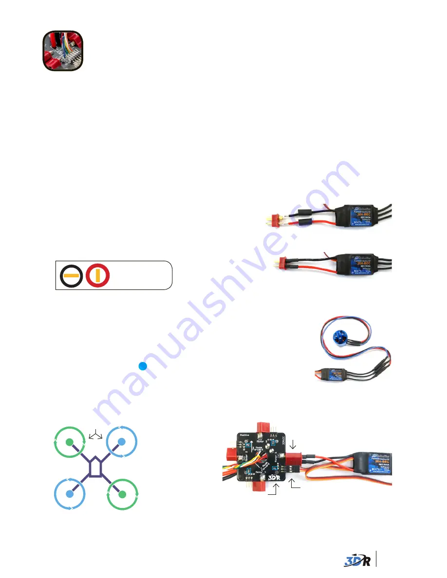
Solder Deans connectors to ESCs:
Add a half-inch length of heat shrink tubing onto
each ESC red wire and black wire. Solder the
positive Deans connector plug to the red wire
and the negative Deans connector plug to the
black wire. Shrink tubing over connections.
Add heat shrink and align wires to correct plugs.
Deans to ESC:
Negative = Black
Positive = Red
- +
Soldered connectors
3
Connect ESCs to motors and PDB
The diagram below indicates the number of each motor. Starting
with the motor labeled
1
, connect the ESC three-wire cable to the
corresponding position on the PDB pins (M1 for motor 1, M4
for motor 4, etc.) with orange wire positioned farthest from the
adjacent Deans connector. Connect ESC Deans connector to PDB
Deans connector for that motor. Repeat for all motors and ESCs.
APM
2
CCW
1
CCW
3
CW
4
CW
APM
1
CCW
2
CCW
4
CW
3
CW
APM
5
CCW
4
CCW
2
CCW
6
CW
1
CW
3
CW
APM
5
CCW
2
CCW
4
CCW
3
CW
6
CW
1
CW
Quad motor order
Blue arms
Motor connected to ESC
Connect motor cable bullet connectors to ESC bullet connectors.
Each ESC should connect to only one motor.
Don’t secure the ESCs to the frame until you have confirmed that each
motor spins in the direction specified in the diagram above (see motor
setup instructions at
copter.ardupilot.com
).
ESC connected to PDB
Deans
Pins
Motor #
labels


