background image

37

6  Smart Shots

Solo’s Smart Shots automate video capturing to make it easy to get stunning aerial video. By default, Cable Cam 
and Orbit are assigned to the controller’s A and B buttons. Use the app to access Selfie or Follow. Smart Shots are 
available only with the Solo app.

When using Smart Shots without a Solo Gimbal, Solo cannot ensure that the subject is in the frame at all times. If 
this is the case, you can improve the chances of keeping the subject in the frame by adjusting the camera mount so 
the camera is fixed at an appropriate angle.

6.1  Selfie

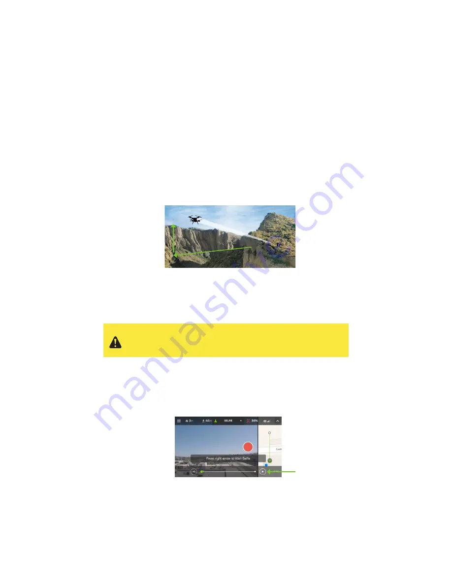
In Selfie, Solo flies a smooth up-and-back path to capture a subject in a cinematic establishing shot. Before starting 
a selfie, always ensure that there is a clear path 200 feet (61 m) behind and above Solo. Once you activate Selfie 
mode, Solo will flies up and away from the subject to a point 164 feet (50 m) from the subject at 82 feet (25 m) 
altitude. 

Figure 6.1.1: Selfie Path and Settings

Distance out (default 164 ft.)

Altitude up (default 82 ft.)

Flight path

6.1.1 

Selfie Setup

To start Selfie, fly Solo to a starting point, facing the subject from approximately 10 feet away, and select Selfie from 
the Shot List. The app will prompt you to press the right arrow to start the selfie.

Figure 6.1.1.1: App - Selfie Activation

2

1

3

Always ensure that there is a clear path 200 feet (30 m) behind and 
above Solo before starting Selfie. Press To stop Solo at any time, 
press Pause. To switch to manual control at any point, press Fly.

Summary of Contents for Solo S110A

Page 1: ...User Manual ...

Page 2: ...8 toll free in the US and Canada Support line hours Mon Fri 8 am to 5 pm PST 3D Robotics 3DR 1608 4th Street Suite 410 Berkeley CA 94710 Tel 1 858 225 1414 3dr com Solo User Manual V7 2015 3D Robotics Inc Solo is a trademark of 3D Robotics Inc GoPro HERO the GoPro logo and the GoPro Be a HERO logo are trademarks or registered trademarks of GoPro Inc ...

Page 3: ...eness 24 4 3 Visual Line of Sight 24 4 4 Flight School 25 4 5 Propellers 25 4 6 GPS 25 4 7 Home Position 25 4 8 Altitude Limit 26 4 9 Emergency Procedures 26 4 10 Flight Battery 27 4 11 Controller 27 4 12 Antenna Configuration 28 5 First Flight 29 5 1 Preflight Checklist 29 5 2 Takeoff 29 5 3 Landing 30 5 4 Return Home 31 5 5 In Flight Data 32 5 6 Joystick Control 33 5 7 App Interface Overview 36 ...

Page 4: ...7 Maximum Altitude Adjustment 49 9 Support 50 10 Maintenance 50 10 1 Controller Battery Replacement 50 10 2 Calibrations 51 10 3 Pairing the Controller 52 10 4 Legs 53 10 5 Battery Tray 56 10 6 Motor Mods 57 10 7 Factory Reset 59 11 Appendix 62 11 1 Specifications 62 11 2 Warranty 63 11 3 Regulatory Compliance 63 ...

Page 5: ...p Shot List 36 Figure 6 1 1 Selfie Path and Settings 37 Figure 6 1 1 1 App Selfie Activation 37 Figure 6 1 2 1 App Selfie Control 38 Figure 6 1 2 2 Controller Selfie Control 38 Figure 6 1 3 1 App Selfie Settings 38 Figure 6 2 1 1 App Cable Cam Setup 39 Figure 6 2 2 1 App Cable Cam Controls 39 Figure 6 2 2 2 Controller Cable Cam Controls 39 Figure 6 2 3 1 App Cable Cam Settings 40 Figure 6 3 1 1 Ap...

Page 6: ...aerial video using a GoPro HERO camera 1 1 2 Controller The controller provides control mechanisms and displays in flight data on a full color screen Using twin long range antennas the controller acts as the central hub for all communication on the 3DR Link network receiving all communications from Solo and the app forwarding telemetry outputs to the app and managing the transmission of all contro...

Page 7: ...s 1 2 3 Orientation LEDs Each arm contains an LED for ground to air directional awareness when armed for flight the two front arms 1 and 3 display white and the two rear arms 2 and 4 display red This LED scheme mimics the headlight and taillight style of a car 1 2 4 Fixed Camera Mount and HDMI Cable Solo includes a GoPro The Frame fixed mount to mount a GoPro HERO camera The HDMI cable connects to...

Page 8: ...t functions starting motors takeoff land and activating GPS flight 1 3 6 Return Home The Return Home button allows you to end your flight automatically at any point by returning Solo to its original launch point and landing 1 3 7 Pause Button The Pause button is Solo s emergency air brake Press Pause to stop Solo and hover in place at any time 1 3 8 Option Buttons The A and B buttons change functi...

Page 9: ...es to elevations less than 2 000 ft above sea level To adjust maximum altitude see Section 8 7 Depending on environmental conditions This top speed corresponds to Solo when operating in Fly mode Maximum speeds for advanced modes may vary see Section 8 1 for more information Antennas Mobile device holder Gimbal controls Joysticks Screen Pause Return home Fly Power Options Estimated flight time up t...

Page 10: ... Navigation in the air is achieved by mixing propulsion of the four motors to actuate flight control along the roll pitch and yaw axes Each of the four motors is numbered by the marking on the arm These numbers correspond to the autopilot calculations for these commands and are used for indicating motor replacement procedures Each motor is controlled by an ESC Electronic Speed Controller that regu...

Page 11: ...button once to display the current power level The Solo Smart Battery ships with approximately 50 charge so charge fully before your first flight for maximum flight time Remove the battery from Solo before charging by holding the release button and sliding the battery towards the back of Solo Charge the battery using the designated Solo charger only using a different charger can damage the battery...

Page 12: ...tup tone Power Solo only with the designated 3DR Solo Smart Battery using a different battery can permanently damage Solo Figure 2 2 2 1 Powering Solo Charge indicator Charge indicator Before powering on make sure Solo is level Also make sure Solo is level before powering on and keep Solo still during startup and while the sensors initialize Moving Solo during this process causes the sensors to ca...

Page 13: ... the side of the controller and to a wall outlet To check the battery level of the controller press the power button A fully charged controller lasts for approximately 6 hours Always check the controller s battery level before you fly and recharge when prompted by the controller The controller takes approximately three hours to charge to 100 Figure 2 3 1 1 Controller Charging 2 3 2 Powering To pow...

Page 14: ...bels from the motors before attaching the propellers Silver top propellers tighten clockwise black top propellers tighten counterclockwise Check the lock and unlock icons on each propeller to see the correct directions for tightening and removing Figure 2 4 1 1 Attach Propellers 2 5 Camera Solo includes a fixed GoPro The Frame mount for your GoPro HERO 3 3 or 4 2 5 1 Attaching To attach the camera...

Page 15: ...our GoPro upside down Connect the HDMI cable Set the GoPro HERO3 to inverted orientation Enable GoPro HERO4 auto orientation Set the GoPro to medium field of view GoPro Settings Camera Orientation GoPro Settings ORIENTATION SETUP OFF OFF UP VIDEO ORIENTATION OFF OFF AUTO VIDEO EXIT EXIT RESETCAM ORIENTATION SETUP OFF OFF UP VIDEO ORIENTATION OFF OFF AUTO VIDEO EXIT EXIT RESETCAM Make sure that the...

Page 16: ...ue Both Solo and the controller must be powered on to connect to the App Figure 2 6 2 1 Connect to Solo Link 2 6 3 Change SoloLink Password Once connected to Solo Wi Fi change your password to secure your SoloLink network Select the Settings menu from the top left drop down and choose Solo to access the options for your drone Figure 2 6 3 1 App Settings Menu In the Solo menu select Wi Fi Settings ...

Page 17: ...te in app Persists until controller update is successful Update complete feedback Tells the user that controller update was successful HAPTIC Three 20 millisecond pulses to communicate update completion A Press required to dimiss same as current implementation Controller updating Update will take about 5 minutes Please ensure charger is connected Controller may go dark while updating Please reconn...

Page 18: ...er must restart as part of the update process your device will lose its connection to Solo Wi Fi When you see the display below select Next to continue Figure 2 6 4 8 App Update Disconnection Confirmation ARTOO UPDATE SCREEN FEEDBACK V10C Update Requirement Screen Controller updated Controller update in progress screen Is displayed after user initiates update in app Persists until controller updat...

Page 19: ... to Sololink wifi Press to continue Returns user to hold Fly button screen Green Solo LEDs showing update complete change to standard red and white when this screen is displayed Required before first flight Use 3DR Solo App to update Waiting for Solo Persists until Solo reconnects or Artoo auto shutdown Press when LEDs are green Update complete Connects to matching version Solo waiting for Solo Ca...

Page 20: ...amera tilt control including angle presets and instant speed adjustment 3 1 In the Box The Solo 3 Axis Gimbal package includes the Solo Gimbal the sunshade four balance weights for the GoPro camera and a screwdriver for installing the Gimbal Figure 3 1 1 Solo Gimbal Parts To install the Solo Gimbal and start utilizing its features follow these Solo Gimbal installation instructions 3 2 Gimbal Insta...

Page 21: ... complete the separation Figure 3 2 1 1 The Frame Removal 3 2 2 Connect Gimbal 1 Remove the foam insert holding the gimbal in place and set it to the side this piece is used to help protect the gimbal during travel 2 On the bottom of the gimbal plate are two ports one for the HDMI cable and one for the gimbal cable Plug in the cables running from Solo to their respective ports on the gimbal as sho...

Page 22: ...al cable 1 Position the gimbal cable out out of the way by pushing any slack towards the front of the Solo Shell Tuck the Gimbal Cable s slack into the front of the Solo body Figure 3 2 3 1 Positioning the Gimbal Cable 2 Loop the HDMI cable around and inside the front of the body pushing any extra slack towards the pocket of Arm 01 as seen below Tuck the HDMI Cable s slack into the side of the Sol...

Page 23: ...n t resting flush with the Solo Shell the most likely cause is that the screws didn t catch correctly If the screws are misaligned do not try to tighten them Back out any crooked screws with the screwdriver then realign them manually before tightening with the screwdriver 3 2 5 Camera Installation Solo includes the 3 Axis Solo Gimbal which holds your GoPro HERO 3 3 or 4 To install your GoPro camer...

Page 24: ...nce Weights Out of the box the Solo Gimbal is perfectly weighted for use with the GoPro HERO4 Black If you are using the GoPro HERO4 Silver or the GoPro HERO3 then you need to add balance weights to optimize these cameras for use with the Solo Gimbal To balance your GoPro attach the corresponding balance weights to the threaded inserts on the top and bottom of the camera housing as shown following...

Page 25: ...e you have the GoPro App downloaded onto your iOS or Android device and that you have an SD card with plenty of available memory installed in your GoPro 2 On the GoPro camera go to Setup and then Wireless Choose the Pair Connect option then GoPro App and then follow the directions 3 Open the GoPro app 4 Connect your camera 5 When you get to the screen with the live video preview tap the downloads ...

Page 26: ...he gimbal up and down You can also set up an automatic tilt control using the 1 and 2 button presets These buttons are located above and below the tilt speed dial as shown in Figure 3 3 1 1 To tilt to a preset angle simply press either button and use the dial to adjust the tilt speed To save a new preset angle hold 1 or 2 Figure 3 3 1 1 Gimbal Controls Resolution 1080P or 2 7K Field of View Medium...

Page 27: ...to troubleshoot the problem 3 3 3 1 The gimbal is not centered with respect to Solo Symptoms The gimbal angle seems cockeyed or the beauty plate at the top of the gimbal does not mount flush with the Solo bottom surface Reason Improper cable routing can cause the gimbal to be off center This also hurts gimbal performance because of interference on dampers Resolution Make sure the HDMI cable is coi...

Page 28: ...ears not to be receiving power Reason Possible connectivity issues Resolution Check the LED on the gimbal behind the GoPro and refer to the color guide in Section 3 3 2 If the LED is off make sure the gimbal connector is plugged in and seated properly If none of the preceding steps resolved your gimbal issue please contact customer support at 3dr com support ...

Page 29: ...ority As the operator you are responsible for knowing and understanding the regulations that govern small unmanned aircraft like Solo in your jurisdiction 4 2 Environmental Awareness Don t fly Solo in extreme weather conditions such as rain high winds snow or fog Such weather conditions can permanently damage Solo or cause instability in flight Before flying determine the boundaries of the safe fl...

Page 30: ... requirements define a GPS lock Reported horizontal position accuracy 16 ft 5 m Reported speed accuracy 2 mph 1 m s Number of satellites 6 Difference between GPS and inertial navigation vertical velocity 2 mph 1 m s If satellite coverage drops beneath a reliable threshold during flight Solo will automatically switch to Fly Manual mode This mode does not provide the flight stabilizing GPS functiona...

Page 31: ...button to stop Solo from hitting an obstacle or to reorient Solo for navigation During Return Home or Land you can pause Solo and stop the landing by pressing Pause Pause is available only with GPS lock 4 9 2 Regain Manual Control Keep the controller easily accessible at all times during flight including during Smart Shots and be prepared to regain manual control at any time To return to standard ...

Page 32: ...ler accessible by the battery door on the back of the controller The controller battery is pre attached to the controller and shouldn t be disconnected unless You plan to store the controller for over three months without using it In this case disconnect the battery from the controller and leave the battery inside the controller to store it You need to replace or upgrade the controller battery Upg...

Page 33: ...t connection to Solo position the antennas down and away from the controller so they are approximately perpendicular to Solo in flight and tilt each antenna out and away from one another at a 20 angle Figure 4 12 1 Controller Antenna Orientation 20 ...

Page 34: ... place Solo at a clear launch point for takeoff at least 20 feet away from you other people and structures 5 2 1 Activating Motors When Solo is ready to fly the controller will prompt you to hold the Fly button to start Solo s motors Hold Fly until the propellers spin Solo is now active ready for takeoff and needs to be treated with appropriate caution to avoid safety hazards To stop the motors pr...

Page 35: ...Cam Orbit 9999FT 700FT HOME 100 FLIGHT BATTERY ALTITUDE FLY 12 GOING TO 5 FT ALTITUDE Cable Cam Orbit 9999FT 700FT HOME 100 FLIGHT BATTERY ALTITUDE FLY 12 FLY Hold to take off FLY Hold to take off Be aware of Solo s orientation before takeoff so you can safely navigate Solo up and away from you once it s in the air If Solo is facing towards you at takeoff move the right stick back if Solo is facin...

Page 36: ...ed when Solo is below 15m Solo first ascends to 25m It then makes its way to the home position set automatically at the beginning of the flight Last it hovers above the home position for five seconds and then lands Figure 5 4 2 Return Home Below 15 m Return Home flying above 15m If a call to Return Home is triggered when Solo is above 15m Solo first ascends 10m It then makes its way to the home po...

Page 37: ...ttery percentage remaining 2 GPS signal strength and number of active satellites 3 Active mode or Smart Shot Fly indicates standard flight 4 Controller battery level 5 Solo Wi Fi signal strength 6 Horizontal distance from the home position launch point 7 Current altitude 8 Currently assigned functions of controller A and B buttons 2 3 4 5 6 7 8 1 ...

Page 38: ... the left stick vertically Figure 5 6 2 Throttle Joystick Behaviors UP DOWN ROTATE LEFT ROTATE RIGHT Left Stick Move the left stick back from center to decrease altitude Set the left stick to center to maintain the current altitude Left Stick Set the left stick fully back to land once Solo is a few inches above the ground Left Stick To take off and to gain altitude move the left stick slightly pas...

Page 39: ...ing right stick controls Figure 5 6 4 Controller Right Joystick Controls Hover Land Lower just slightly to hover Left Yaw Left Right Right Yaw Deactivate Hold until propellers stop spinning Lower just slightly to hover Left Yaw Left Right Right Yaw Deactivate Hold until propellers stop spinning Move the stick to the left to rotate counterclockwise Move the stick to the right to rotate clockwise Le...

Page 40: ...op spinning Move the right stick forward to fly forward Move the right stick back to fly backward Activate Hold until propellers tart spinning ake off Lift Raise just slightly or take off Hover Land ower just slightly o hover eft Yaw Left Back Forward Right Right Yaw Deactivate Hold until propellers top spinning Activate Hold until propellers tart spinning Take off Lift Raise just slightly or take...

Page 41: ...recording to mobile device requires Solo Gimbal 11 Alerts and instructions 5 7 1 Map View To access the small map view swipe left from the right edge of the app To full screen the map swipe left again To hide the map tap the video display The map view is available only with GPS lock and on devices with cellular Internet 5 7 2 Shot List To access the Shot List select the active mode or shot from th...

Page 42: ...matic establishing shot Before starting a selfie always ensure that there is a clear path 200 feet 61 m behind and above Solo Once you activate Selfie mode Solo will flies up and away from the subject to a point 164 feet 50 m from the subject at 82 feet 25 m altitude Figure 6 1 1 Selfie Path and Settings 1 Distance out default 164 ft 2 Altitude up default 82 ft 3 Flight path 6 1 1 Selfie Setup To ...

Page 43: ...lo forward and back along the Selfie path To stop Solo at any time press Pause To exit to standard flight press Fly Figure 6 1 2 2 Controller Selfie Control 6 1 3 Settings To access the settings from the in flight Selfie interface select the option icon with the three dots in the bottom right To adjust distance out altitude up and cruise speed use the sliders For instructions and tips select Selfi...

Page 44: ... Cam Setup 6 2 2 Cable Cam Operation To control Cable Cam through the app tap the right arrow to move towards point A and tap the left arrow to move towards point B Cable Cam s default cruise speed is set to 9 mph 4 m s Figure 6 2 2 1 App Cable Cam Controls To operate Cable Cam using the controller move the right stick to the left to fly towards point A and to the right to fly towards point B To p...

Page 45: ...ation of the subject on the map If it s necessary to correct the subject s position on the map fly Solo to the desired location then press A on the controller to lock on to the subject Once you set the orbit subject the App displays a Subject Locked confirmation To adjust the position of the subject during Orbit move the center point on the map Figure 6 3 1 1 App Orbit Setup 6 3 2 Orbit Operation ...

Page 46: ...tings 6 4 Follow Follow creates a virtual tether between Solo and your mobile device allowing Solo to track you as you move If the Follow subject is engaged in an activity that prevents them from using the controller you are required to use a safety pilot during Follow The subject carries the mobile device and is followed by Solo and the safety pilot holds the controller and is ready to regain man...

Page 47: ...by moving the right stick vertically and orbit the subject by moving the right stick horizontally To adjust Solo s altitude during Follow move the left stick vertically And to override the camera tracking and temporarily pan the camera move the left stick horizontally To stop Solo during Follow press Pause the camera continues to track the subject To exit to standard flight press Fly Figure 6 4 2 ...

Page 48: ...se wait Level error User is asked to use Solo app to calibrate Alert persists until User complete calibration using the app sys then continues sensor chec Powers off controller or Solo Controller auto shutdown Note Artoo will not assume the same error is present on restart and will run a fresh check when connected to Solo Uneven surface Move Solo to a level surface Altitude calibration System self...

Page 49: ...te Alert persists until User completes calibration using the app system then continues sensor check User powers off controller or Solo Controller auto shutdown Note Artoo will not assume the same error is present on restart and will run a fresh check when connected to Solo Calibrating compass Please wait Level error User is asked to use Solo app to calibrate Alert persists until User complete cali...

Page 50: ...or check Timeout after 1 minute results in sensor error screen Landing Complete Screen showing automatic landing is complete Alert persists until TIMEOUT 3000 milliseconds Controller connection poor Banner Appears once connection strength is below average performance for X time TIMEOUT After 3000 milliseconds 324FT 84FT HOME 48 FLIGHT BATTERY ALTITUDE FLY 12 3DR Solo app connected 324FT 84FT HOME ...

Page 51: ...onds HAPTIC 40 millisecond buzz for awareness GPS ready GPS signal established User took off without GPS no home position regardless of advanced modes Alert persists until user sets home HAPTIC 20 milliseconds every 3 seconds until press GPS found FLY Press to set home Switching to FLY Fullscreen message Times out after 5000 milliseconds Modified Telem screen Version 1 Now shows new mode A B funct...

Page 52: ...ze does not require GPS lock 8 1 3 Drift Drift modes requires GPS lock and provides a plane like flying experience Drift is ideal for navigating Solo using the video feed This is known as first person view FPV and provides an immersive flying experience In drift you control roll pitch and yaw with the controller s right stick To navigate Solo in drift move the right stick to initiate a coordinated...

Page 53: ... Modes option to gain access to Solo s advanced modes Figure 8 2 1 App Advanced Settings 8 3 Accessing Advanced Flight Modes Once enabled advanced flight modes can be accessed only be assigning them to the controller s A and B buttons using the app In the app select Preset A or Preset B from the Solo menu The app must be connected to Solo to apply button assignments Once assigned use the controlle...

Page 54: ...e for slower more cushioned movement or move the slider towards the rabbit for faster more responsive movement Figure 8 5 1 App Performance Sliders 8 6 Units To change the units in the Solo App between imperial and Metric select Units from the Settings menu Figure 8 6 1 App Change Units 8 7 Maximum Altitude Adjustment To adjust the altitude limit select Altitude Limit from the Solo menu If you cho...

Page 55: ... designed to absorb impact from hard landings and protect the core electronics If damage is sustained to Solo s legs or motors replace them with official 3DR parts from store 3dr com or an authorized retailer 3DR offers an extended controller battery upgrade with double the capacity so you can fly longer between charges Before opening the battery bay or performing any maintenance on Solo always en...

Page 56: ...ctures before starting calibration Figure 10 2 1 1 App Compass Calibration Setup The app will prompt you to rotate Solo end over end multiple times until the bar at the top of the screen is completely green If the calibration fails move to a different location and try again Figure 10 2 1 2 App Compass Calibration Procedure 10 2 2 Level Calibration A level calibration zeroes Solo s accelerometers t...

Page 57: ... a small screwdriver or another similar tool to push it Figure 10 3 1 Pair Button 5 Press the Pair button underneath Solo and hold for one second 6 When the controller detects Solo it prompts you to accept the pairing request as seen in the screen below If the controller does not detect Solo after thirty seconds try pressing the Pair button underneath Solo again and repeat as needed Figure 10 3 2 ...

Page 58: ...ve the two screws detach the old leg and attach the new leg using the provided screws Figure 10 4 1 1 Standard Leg Replacement Process 10 4 2 Legs 1 and 2 with Antennas To replace a leg with an antenna module where the existing antenna is physically intact you ll need to remove the antenna from the old leg before replacing it To detach the antenna remove the plastic sheet from the leg 1 and detach...

Page 59: ...nly the yellow backed Velcro strip to the Velcro on the antenna Then remove the backing and attach the Velcro and antenna to the inside of the leg placing the tip of the antenna five mm from the edge of the rubber foot 1 as shown in the following illustration Fold the ends of a provided plastic sheet at right angles 2 remove the adhesive backing and stick the plastic sheet to the leg so it secures...

Page 60: ...eg being replaced Disconnect the compass connector from the board by holding down the tab on the far side of the connector and lifting up the connector Because the space between the arm and the connector is limited it might help to use a screwdriver to press the tab Figure 10 4 3 1 Compass Connector on Mainboard With the compass disconnected remove the old leg and cable from Solo Place the new leg...

Page 61: ...ing tool to loosen the four clips along the back edge of the cover Figure 10 5 1 1 GPS Cover Removal 10 5 2 Battery Tray Removal To detach the battery tray and access Solo s main electronics bay use a small Philips screwdriver to remove the seven screws securing the battery tray to Solo Figure 10 5 2 1 Battery Tray Removal The battery tray will still be connected to Solo via the GPS cable so caref...

Page 62: ...ll flat prying tool to remove the LED cover form the underside of the arm Figure 10 6 1 LED Cover Removal Use a 2 Phillips screwdriver to remove the four screws securing the pod to the arm Figure 10 6 2 Motor Pod Removal Disconnect the wide beige connector the red wire and the black wire to remove the old motor pod To remove the wide beige connector DF13 carefully lift the edges of the connector a...

Page 63: ...les inside the arm and set the new pod into place Figure 10 6 4 Motor Pod Connection Turn over Solo and secure the new motor pod into place using the four provided screws Do not reuse the screws from the old Motor Pod Finally snap the LED cover back into place Figure 10 6 5 Motor Pod and LED Cover Attachment 1 2 ...

Page 64: ...ld Solo s Pair button while powering on Solo Make sure you feel the Pair button click down underneath the paper clip to verify you have properly activated the Pair button Continue holding the Pair button for at least 15 seconds Figure 10 7 1 Pair Button Be low the Accessory Port and adjacent to the Pair button is a small orange LED Pair indicator light Once this light starts flashing rapidly strob...

Page 65: ...followed by a sequence of beeps When the lights stop changing color the reset is complete Upon completion the lights will freeze on their current colors so they might all be the same or different colors Step 3 Reboot Solo and the Controller While rebooting Solo emits its regular startup tones The lights underneath Solo s arms also light up green and change to white in the front and red in the back...

Page 66: ... and the Controller For instructions how to pair Solo and the Controller see section 10 3 Step 5 Update your system For instructions how to update your system see section 2 6 4 The Factory Reset procedure is now complete ...

Page 67: ...xtended battery Power Electric rechargeable lithium polymer battery Battery Lithium polymer 5200 mAh 14 8 Vdc Battery weight 1 lb 5 kg Estimated flight time 25 minutes Maximum altitude 328 ft 100 m Range 5 miles 8 km Payload capacity 1 1 lbs 500 g Cruise speed 5 7 mph 2 5 m s Maximum speed 55 mph 25 5 m s Maximum climb rate 11 mph 5 0 m s Maximum descent rate 5 5 mph 2 5 m s Headwind limitation 25...

Page 68: ...s As Is and any third party warranties products software services maintenance or support are provided by the original manufacturer or supplier not by 3D Robotics Software is subject to the separate software license agreement accompanying or made available to you in connection with the software A portion of the software contains or consists of open source software which you may use under the terms ...

Page 69: ...ndesired operation of the device Le présent appareil est conforme aux CNR d Industrie Canada applicables aux appareils radio exempts de licence L exploitation est autorisée aux deux conditions suivantes 1 l appareil ne doit pas produire de brouillage et 2 l utilisateur de l appareil doit accepter tout brouillage radioélectrique subi même si le brouillage est susceptible d en compromettre le foncti...

Page 70: ......

Reviews: