background image

5


THERMAL GIMBAL FOR 3DR SOLO MANUAL


FLIR VUE/VUE PRO Installation


CONNECTING THE GIMBAL TO THE VUE/VUE PRO SERIES THERMAL CAMERAS:


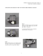
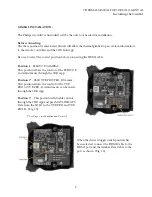
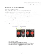
Step 3:


Plug the USB connector on the gimbal, into the 
VUE Series Camera and secure using the four 
short allen-head screws provided.  (Fig. 6)


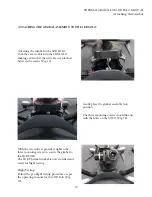
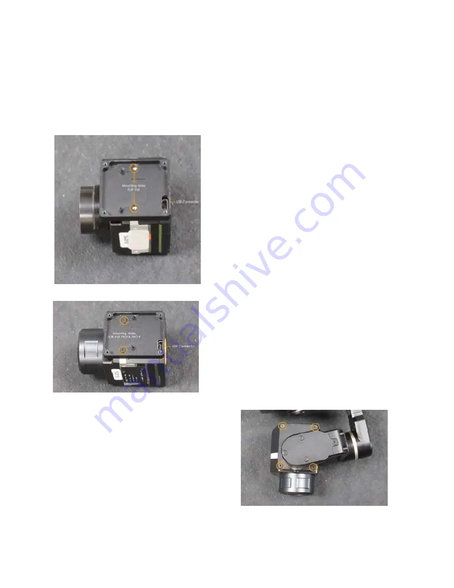
Step 2:


Align to the USB Connector to the cover plate. 
The holes are aligned differently on the VUE 
PRO/PRO-R.  (Fig. 4&5)


Use the long allen-head screws provided, to 
mount the plate on the camera.


Summary of Contents for Solo

Page 1: ...ThermalGimbal for the 3DR SOLO Installation Instructions P O Box 4242 Middletown New York 10941 USA Phone 1 888 919 2263 Outside the U S 1 845 343 4077 Fax Line 1 845 343 4299 Version 1 3 10MAR2017...

Page 2: ...recommended to wait until the product returns to room tem perature before turning iton Store the product in a dry and clean environment when storing the product for along period of time Do not disconn...

Page 3: ...e com Toll Free 1 888 919 2263 Outside the US 1 845 343 4077 The VUE PRO Series modifications will allow you to control the following parameters remotely via the 3DR Solo APP Color Palette 3 Choices C...

Page 4: ...MBAL TO THE 3DR SOLO Before installing the camera to the Gimbal please remove the battery and any other power source that may be connected FLIR VUE PRO R USERS Before you begin please remove the FLIR...

Page 5: ...RAS Step 3 Plug the USB connector on the gimbal intothe VUE Series Camera and secure using the four short allen head screws provided Fig 6 Step 2 Align to the USB Connector to the cover plate The hole...

Page 6: ...from the 3DR SOLO Removing the cover plate If there is no Gimbal attached the cover plate will need to be removed The plate is attached with three screws on the 3DR SOLO Loosen the self retaining scr...

Page 7: ...moved before installing the 3DR Solo Thermal Gimbal Assembly Loosen the three self retaining screws with the provided Phillips screwdriver Carefully lift up the Gimbal assembly from the drone while pr...

Page 8: ...essing the locking tab and gently lifting the connec tor straight up from the board as shown Fig 11 12 To disconnect the HDMI cable gently sepa rate the cable from the connection by pulling away from...

Page 9: ...ble Position 1 FLIR VUE CAMERA This position allows the control of the FLIR VUE and adjustments through the 3DR App Position 2 FLIR VUE PRO PRO R Camera This position allows the control of the VUE PRO...

Page 10: ...between the seams Fig 17 With the screwdriver provided tighten the three mounting screws to secure the gimbal to the 3DR SOLO The 3DR Thermal Gimbal is now installed and ready for flight testing Flig...

Page 11: ...provided leg extensions for the 3DR SOLO To Install First remove the existing feetfrom the 3DR SOLO Legs by pulling straight up Store in a safe place for future use Fig 20 Install the leg extenders b...

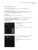
Page 12: ...tion PWM Settings These setting changes should be performed prior to flight NOTE Before you begin be sure that the settings are set to the following suggested values PWM s cannot share the same config...

Page 13: ...TWO State Low Set to Stop Recording This will send the signal to stop recording to the FLIR VUE PRO PRO R SD Card State High Set to Start Recording This will send the signal to begin recording to the...

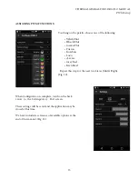
Page 14: ...will happen with the assigned control Fig 28 The number of states can be set to two or three In this example we have chosen three This setting will allow us to choose between three palettes during fli...

Page 15: ...Fusion Ironbow Lava Arctic GreyRed InstAlert Repeat this step for the next two States Mid High Fig 30 When Configuration is complete touch on the back arrow to the Settings Accy Port screen These set...

Page 16: ...s example we chose Arctic PLEASE NOTE These states cannot change while recording Controlling the Thermal Camera through the GoPro App Control panel Wehave adapted the Thermal Gimbal to work with the 3...

Page 17: ...no SD Card option on the FLIR VUE The area just above the button contains status icons From left to right these are Camera Roll recording video to the mobiledevice Camera Icon recording video to the...

Page 18: ...gs areas available from the buttons on the right side of the screen are Camera Mode and Camera Settings Camera Mode Will only work in Video Mode to record continuous video start and stop Photo Burst M...

Page 19: ...on MAVLink The VUE PRO VUE PRO R can be configured to use this bus to capture available telemetry data provided by GPS altimeter accelerometers etc This data is saved as standard EXIF metadata in Stil...

Page 20: ...s standard for most devices The Vue Pro can save image data in a number of file formats each with unique characteristics The common file types are JPEG The JPEG format of the Vue Pro has both the comp...

Page 21: ...Hot and BlackHot are the primary palettes used in thermal imaging The image has been described as containing 256 shades of gray each representing a different temperature range present in the scene A v...

Page 22: ...so that changes in image content will not alter the apparent brightness and contrast This will also suspend FFC events Operating in this mode could negatively impact image quality Table 1 3 GPS MODE...

Page 23: ...r certain conditions Different color palettes can provide very different results in the image Their appeal is based on personal preference Table 2 1 Digital Zoom FLIR Vue digital zoom can be assigned...

Page 24: ...nty service or repair Customer must first obtain a returned material authorization RMA number from RHP INTERNATIONAL To obtain the RMA number Owner must provide an original proof of purchase For addit...

Reviews: