background image

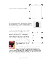
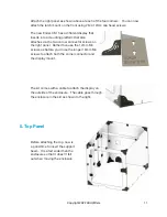
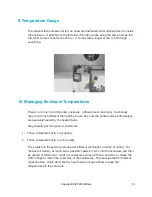
Use access through the doors to attach 
the top of the enclosure using M4 12mm 
screws.  You’ll attach the top on the four 
corners, and to each of the mid-panel 
connectors as well.  The slit is towards 
the front, and the small access hole for 
the filament runout sensor cable should 
be on the right.  The view shown at the 
right is from above facing the front of the 
printer.

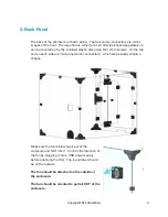
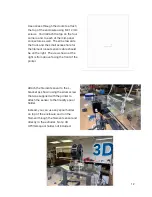
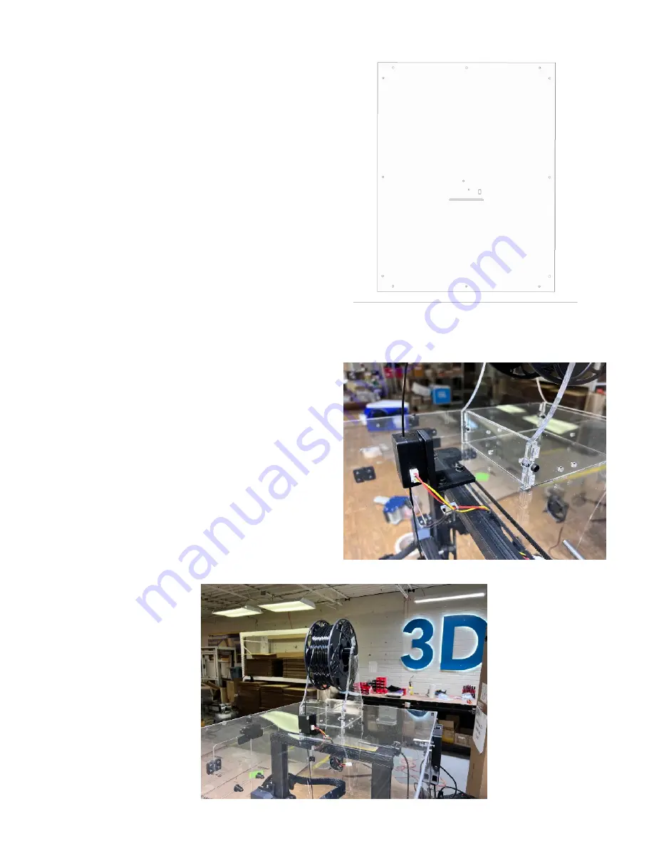
Attach the filament sensor to the L-
bracket as shown using the silver screw 
that was supplied with the printer to 
attach the sensor to the Creality spool 
holder.  

Instead, you can use any spool holder 
on top of the enclosure and run the 
filament through the filament sensor and 
directly to the extruder.  Note: 3D 
UPfitters spool holder not included.

Copyright 2022 3DUpfitters

12

Summary of Contents for Ender 3 S1 Enclosure Kit

Page 1: ...Ender 3 S1 Enclosure Kit Installation Manual 1 0 April 2022 Copyright 2022 3DUp fi tters 1 ...

Page 2: ...This page intentionally left blank Copyright 2022 3DUp fi tters 2 ...

Page 3: ...or the Creality Ender 3 S1 ONLY The Ender 3 V1 V2 and Max all require di ff erent enclosures If you have a di ff erent version of the enclosure please read previous versions of the manual available on the website Is your Printer Customized If your printer is stock then no customization is needed If you have customized the printer you should examine any modi fi cations to make sure they don t block...

Page 4: ...hite covering to protect against scratches Follow the directions below to remove the cover and discover the beautiful plastic underneath To remove the covering from an acrylic panel lay the panel fl at on a table Then peel up a corner of the covering and CAREFULLY and SLOWLY pull horizontally to the sheet to reduce the lateral forces that would bend the acrylic This video shows just what to do Cop...

Page 5: ...s to attach the fan and or fi lter will vary depending on the depth of the particular shipment of fans we happen to get that month They won t be hard to spot since they ll be the longest thing in the bags Finally and we can t stress this enough D O N T O V E R T I G H T E N T H E S C R E W S Leave the screws a little loose until the end adjustment phase During that process you ll be hand tightenin...

Page 6: ...In all cases the surface of the connector with the cutout pattern faces front or back The front door is designed so that the latches are on the left Attach the corner connectors on the back side of the door frame using the provided cap head 12mm screws See the photos below The top of the connector should be fl ush with the top of the acrylic There are also smaller connectors at the top and right s...

Page 7: ...ach the hinges to the door and door frame using M4 12mm screws and nuts There will be some play in the hole size so that you can adjust the door to swing freely Attach the doorknob by fi rst inserting the square M4 nut into the slot Use a 16mm cap head screw to attach the door Now that the latches are mounted it is time to connect the strike plates Each plate comes with a squishy adhesive covering...

Page 8: ...the side door will be in a separate packet Attach the door hinges latch mounts strike plates and the knob and the assembly will look like the illustration to the right Don t forget the mid panel connectors at the back left and top As with the front door adjust how the door hangs by loosening the hinge screws using the strike plates to hold the door to the latches and then tightening the hinge scre...

Page 9: ...e top and on each side are mid panel corner connectors which are basically simple L shapes Make sure the fan is blowing air out of the enclosure and NOT into it Con fi rm the direction of the fan by plugging it into a USB power supply before attaching the fi lter The round label should be on the outside The fan should be attached on the outside of the enclosure The fan should be oriented to pull a...

Page 10: ...portal Locate the grommet and insert it into the grommet holder This is where you ll insert the power cable USB cable and any other wires you want to run in or out of the enclosure Insert the grommet holder grommet combination into the U shaped hole in the right side panel This will enable you to slide the enclosure o ff and onto the printer without unplugging the cables 4 Right Panel Copyright 20...

Page 11: ...nel Rather than use the 12mm M4 screws as before you ll use the longer 16mm M4 screws to attach both the corner connector and the display mount The kit comes with a cable to attach the display on the outside of the enclosure The cable goes through the enclosure in the slit as shown to the right 5 Top Panel Before attaching the top now is a good time to insert the support beam It is a tad wider tha...

Page 12: ...uld be on the right The view shown at the right is from above facing the front of the printer Attach the fi lament sensor to the L bracket as shown using the silver screw that was supplied with the printer to attach the sensor to the Creality spool holder Instead you can use any spool holder on top of the enclosure and run the fi lament through the fi lament sensor and directly to the extruder Not...

Page 13: ...able in many places online to remove the clog This technique is easy and works most of the time It is acceptable to turn o ff the fan when printing ABS or ASA in order to bring the temperature into the ideal range but be sure to turn the fan back on when you re fi nished especially if you are venting or fi ltering the air to remove VOCs Note that the lid fi ts right into the vent slots helping to ...

Page 14: ...e product going around the enclosure looking to make sure all of the panels are fl ush to each other 8 Assemble Spool Holder Instructions to assemble the spool holder are available online in the product description but it s not too hard to just wing it The location that will give the least resistance is placing the spool holder directly to the left of the printer Many people who are low on space h...

Page 15: ...rs since both designs are passively heated by the heated beds We generally get two types of customers 1 Those interested mostly in air quality 2 Those interested mostly in print quality The problem is those two goals use two di ff erent techniques in terms of air fl ow For the best air quality as much air as possible needs to come into the enclosure and then be vented or fi ltered out All of our e...

Page 16: ...o the later on a couple of machines where the temperature when printing ABS gets as high as 46C They ve been running like that for years with no clogging and even with no venting of the power supplies we ve never had a power supply fail either Obviously your mileage may vary as it depends on a lot of variables such as fi lament quality and the quality of the power supply in your printer If you re ...

Reviews: