
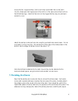
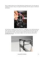
Locate the two magnet latches, one for each door, and attach them to the latch
mounts. Make sure the magnet part of the latch is on the same side of the mount as
the 3DUpfitters logo. Note that the colors of the magnet latches may vary between
production runs.
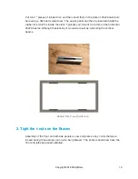
Attach the latches to the latch mounts using the provided small wood screws. Do not
over tighten or they may strip. The distance from the edge of the metal pieces in the
latch to the front edge of the latch mount should be 1/4”.
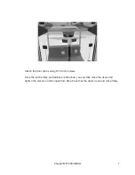
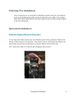
Once the latches are attached to the latch mounts they can be attached to the
horizontal 20x20 pieces using 10mm M5 bolts and M5 nuts as shown.
7. Finishing the Doors
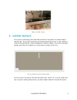
Now that the latches are mounted its time to connect the strike plates. Each plate
comes with a squishy adhesive covering the same size of the plate. Carefully attach
the adhesive side to the acrylic at the top of the door. Then, adjust the width of the
metal strike plate so that it is held on by the pressure of the two sides of the plate. The
adhesive covering will keep the metal of the strike plate from scratching the acrylic.
Copyright 2018 3DUpfitters
6