background image

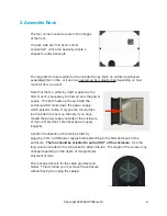
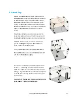
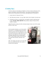
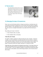
The back should look like the illustration to the right 
when you’re finished.

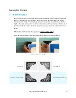
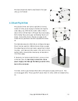
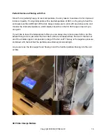
4. Attach Right Side 

The purpose of the vent on the right side is to bring 
cooler air to the power supply to increase its longevity 
under heavy use. With the fan and/or carbon filter in 
place cold air will be drawn in through the power supply, 
both cooling the power supply and heating the air as it 
enters.  Even without a fan, the power supply is still 
cooler this way because one side is exposed to colder 
air.

The right side panel is a little tricky to configure because 
Prusa now has used two di

erent sizes of power supply.  

The default layout is for silver power supply they’ve used 
for years.  Just make sure the cutout in the vent is on the 
bottom half to fit around the small bump at the bottom 
1/3 of the supply.

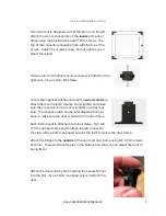
If, however, your power supply is black, you’ve got one 
of the new ones.  

In that case you’ll want to run its 

power supply cord through the black grommet in the 
back of the enclosure.


You’ll also notice a gap between the bottom of the power supply and the vent.  This 
can be plugged with a “Prusa gap filler” piece, shown in white, which is included in the 
kit. 

Copyright 2020 3DUPfitters LLC

10

Summary of Contents for Prusa i3 MK2

Page 1: ...Prusa i3 MK2 3 3S Enclosure Kit Installation Manual 4 0 October 2020 Copyright 2020 3DUPfitters LLC 1 ...

Page 2: ...This page intentionally left blank Copyright 2020 3DUPfitters LLC 2 ...

Page 3: ...r Kit This installation manual covers the R3 enclosure design for the Prusa i3 MK2 MK2S MK3 MK3S enclosure If you have the Prusa MMU or Prusa Mini enclosures this is NOT the right manual Is your Prusa Customized If your printer is stock then no customization is needed If you have customized the printer you should examine any modifications to make sure they don t block the panels If part of one of ...

Page 4: ...t against scratches Follow the directions below to remove the cover and discover the beautiful plastic underneath But if in some rare instance the plastic arrives with a crack or scratch either from manufacturing or shipping we ll of course replace it for free To remove the covering from an acrylic panel lay the panel flat on a table Then peel up a corner of the covering and CAREFULLY and SLOWLY p...

Page 5: ... filter will vary depending on the depth of the particular shipment of fans we happen to get that month They won t be hard to spot since they ll be the longest thing in the bags Finally and we can t stress this enough D O N T O V E R T I G H T E N T H E S C R E W S D O N T U S E A P O W E R S C R E W D R I V E R Leave the screws a little loose until the end adjustment phase During that process you...

Page 6: ...re identical i e Bottom Right is the same as Top Left In all cases the surface of the connector with the cutout pattern faces front or back Note the two pictures below show the inside of the front panel If the holes don t seem to line up please check out this video https www 3dupfitters com blogs news how to attach corner connectors R Connector From Inside Top Left L Top Right R Bottom Left Labele...

Page 7: ...nts Hand tighten and make sure they re secure but do not over tighten or they may strip The magnetic latch can be later adjusted front to back to make sure the door is flush with the door frame Each latch mount is attached via three screws Two M4 12mm cap heads are used to attach the latch mount to the side while a 30mm cap head secures the latch mount to the door frame Attach the hinges to the ou...

Page 8: ... left side of the door in place and then placing the front on its side so the hinges are at the top and the latch at the bottom Loosen the screws and adjust the position of the hinges so that there s an even gap on all sides of the door The door should open and close freely When the front is finished it will look like the image to the right 2 Attach Left Side The left panel is distinguishable by i...

Page 9: ... power supply which extends its life Only use the circular disk not included to cover up the hole if you have moved the power supply outside of the enclosure or if you simply don t care about power supply longevity Confirm the direction of the fan s air filter by plugging it into a USB power supply before attaching to the filter and back of the enclosure The fan should be oriented to pull air OUT ...

Page 10: ...he right side panel is a little tricky to configure because Prusa now has used two different sizes of power supply The default layout is for silver power supply they ve used for years Just make sure the cutout in the vent is on the bottom half to fit around the small bump at the bottom 1 3 of the supply If however your power supply is black you ve got one of the new ones In that case you ll want to...

Page 11: ...fore tightening the mid corner connectors With the beam in place it s time to remove the plastic First lay the top on a flat surface as shown in the instruction video https www 3dupfitters com blogs news acrylic Be careful as the area around the filament slit will crack if handled roughly The top has a front back and left to right This is because it overhangs the front which is twice as thick The ...

Page 12: ...ts are sturdy but they re still all made out of plastic Repeat the process going around the enclosure looking to make sure all of the panels are flush to each other Once the gaps are sealed you can then position the enclosure The biggest thing with the power supply is to get the vent in the right place If you are using the silver power supply there isn t much tolerance in the placement of the off o...

Page 13: ...rip available just about anywhere That way you can power both the printer and accessories from the same strip AND turn everything off and on from outside the enclosure 8 Spool Holder Instructions for assembling the spool holder are available online You can simply sit the spool holder on the top of the enclosure where the filament can fit into the slit Of course you are free to use whatever type of ...

Page 14: ... quality 2 Those interested mostly in print quality Think Airflow Not Fishtank The problem is those two goals use two different techniques in terms of airflow For the best air quality we use the same design as industrial equipment which uses airflow to manage air quality Because of physics the amount of air moving into the enclosure has to be equal to the air moving out of the enclosure When the ai...

Page 15: ...for filaments like ABS which happens naturally because the recommended bed temperatures are much higher With the fans turned on we shoot for internal temps between 35C and 40C for 3D printers that use E3D hot ends because E3D recommends that temp range to avoid clogging Keeping the temperatures in that range it puts the least stress on the equipment and follows the manufacturer s guidelines This w...

Page 16: ...be in the 30 35C range or lower if you can get it If you d like to lower the temperature further you can always buy a more powerful fan but the easiest thing to do is just crack the front door a little to increase airflow But won t that let out all of the volatile organic compounds coming off the hot end The key is the negative pressure combined with the fact that the particles are extremely small ...

Page 17: ... your current temperatures before attempting to make any changes We get support calls saying my enclosure is too hot or too cold but they didn t actually measure the temperature Without measurements it s impossible to say if a printing problem is temperature related or not 11 DIY Tool Holder Our favorite customization is to add magnetic tool holders to the side One end can be attached via the same...

Page 18: ...ingiverse Using your favorite STL editor you can add 2mm to the right Then purchase these bumpers to place on the bottom of the feet and your Prusa will be quieter than ever AND match the vent hole on the enclosure Copyright 2020 3DUPfitters LLC 18 ...

Reviews: