background image

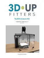
Taz6 Enclosure Kit 

Installation Manual 2.0  

April 2022


Copyright 2020 3DUpfitters

1

Summary of Contents for Taz6 Enclosure Kit

Page 1: ...Taz6 Enclosure Kit Installation Manual 2 0 April 2022 Copyright 2020 3DUp fi tters 1 ...

Page 2: ...This page was intentionally left blank Copyright 2020 3DUp fi tters 2 ...

Page 3: ... installation manual covers the R2 enclosure design for the Taz6 enclosure If you have a di ff erent version of the enclosure please read the correct manual version available on the website Is your Taz6 Customized If your printer is stock then no customization is needed If you have customized the printer you should examine any modi fi cations to ensure they don t block the panels If part of one of...

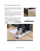
Page 4: ...hite covering to protect against scratches Follow the directions below to remove the cover and discover the beautiful plastic underneath To remove the covering from an acrylic panel lay the panel fl at on a table Then peel up a corner of the covering and CAREFULLY and SLOWLY pull horizontally to the sheet to reduce the lateral forces that would bend the acrylic This video shows just what to do Cop...

Page 5: ...Warning Please do not move the Taz6 when the enclosure is installed If you need to move the Taz6 itself remove the enclosure by lifting it straight vertically Copyright 2020 3DUp fi tters 5 ...

Page 6: ...se the speci fi ed screw for the best results The actual length of the long screws to attach the fan and or fi lter will vary depending on the depth of the particular shipment of fans we happen to get that month They won t be hard to spot since they ll be the longest thing in the bags Assemble Panels The front panels are thicker 1 4 acrylic to provide more structural rigidity for the doors Do not ...

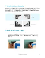
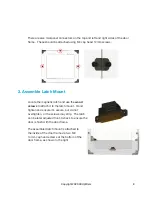
Page 7: ...Right is the same as Top Left In all cases the surface of the connector with the cutout pattern faces front or back 2 Attach The Door Frame Corners The front door is designed so that the latches are on the left Attach the door connectors on the backside of the door frame using the provided cap head 14mm screws See the photos below The top of the connector should be fl ush with the acrylic top Top ...

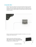
Page 8: ...wood screws to attach it to the latch mount Hand tighten and ensure it s secure but do not overtighten or the screws may strip The latch can be later adjusted front to back to ensure the door is fl ush with the door frame The assembled latch mount is attached to the inside of the door frame via two M4 14mm cap head screws at the bottom of the door frame as shown to the right Copyright 2020 3DUp fi...

Page 9: ... the front panel There can be slight variations in the laser angle so the door works best if the same orientation Attach the doorknob by fi rst inserting the square M4 nut into the slot Use a 16mm cap head screw to attach the door Attach the strike plate by attaching the adhesive rubber backing to the acrylic The black square strike plate should then fi t snuggly over the backing If there is slipp...

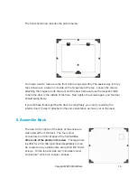
Page 10: ...f you still have trouble getting the door to swing freely you can try reversing the interior door if it wasn t attached in the same orientation as it was cut on the laser 5 Assemble Back The view to the right is of the back of the enclosure when viewed from the back The four corner connectors are mirror images of the front on the other side of the plastic in this view The large hole is either for ...

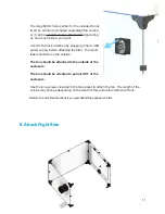
Page 11: ...ttaching the fi lter The round label should be on the outside The fan should be attached to the outside of the enclosure The fan should be oriented to pull air OUT of the enclosure Use the long screws included in the fan packet to attach the fan The length of the screws may change depending on the depth of this particular shipment of fans Refer to the Air Filter directions if you purchased the opt...

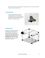
Page 12: ...air fi lter it helps bring in air from the outside to run through the fi lter 8 Attach Top Place the top on the existing three sides and attach it to the corner and mid panel connectors The enclosure will now look like the picture to the right Note that on models with a 6mm front and 3mm sides the top has a front and a back The holes on the front are positioned so that the top fi ts over the front...

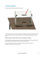
Page 13: ...mmodate the electronics case s back Slide the enclosure around the Taz6 so that it is approximately in the center Place the left front panel around the electronic enclosure to get a feel for how it fi ts snugly against the case and then move the enclosure into position to line up with the holes Attach the front left panel with screws reaching through the front door to reach the nuts Repeat the pro...

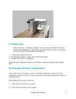
Page 14: ...ld it there 3 Re tighten the screws to hold the panel Repeat the product going around the enclosure looking to make sure all panels are fl ush with each other 20 Managing Enclosure Temperatures There s not much to a 3D printer enclosure Although ours look fancy they re not much di ff erent from putting a card box over the printers since both designs are passively heated by the heated beds We gener...

Page 15: ... an acceptable risk might want to run higher temperatures for minor warping of ABS parts or print nylon In those cases you can turn o ff the fans or even print one of the vent covers and not vent at all We do the latter on our internal print farm on a couple of machines where the temperature when printing ABS gets as high as 46C They ve been running like that for years with no clogging and even wi...

Reviews: