29000132-001 A
9
Chapter 2: Hardware installation
Preparation for Use
The 3e Technologies International's 3e-525A Wireless Access Point requires
physical mounting and installation on the site, following a prescribed placement
design to ensure optimum operation and roaming.
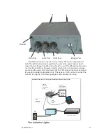
The 3e-525A operates with Power over Ethernet (PoE) which requires the
installation of a separate Power injector which “injects” DC current into the Cat5
cable.
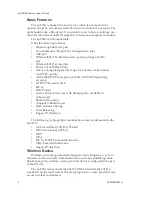
The 3e-525A package includes the following items:
• The 3e-525A Wireless Access Point
• 3 attachable 5dBi omni-directional antennas with reverse polarity type N
connectors
• 1 15 Meter Ethernet cable
• 1 Power injector
• 1 mounting kit for unit
• 1 Ground wire
• Documentation as PDF files (on CD-ROM)
• Registration card
• Warranty card
The 802.11g antenna port is used when configuring the unit to be used as a
bridge. The 802.11g port uses an omni-directional antenna.
The 3e-525A can be mounted outdoors on a high post to achieve the best
bridge result. It has a lightening protection option to prevent lightning damage.
The antennas used with the 525A must be installed with a minimum sep-
aration distance of 20 cm from all persons, and must not be co-located or
operated in conjunction with any other antenna or transmitter. Installation
should be accomplished using the authorized cables and/or connectors provided
with the device or available from the manufacturer/distributor for use with this
device. Changes or modifications not expressly approved by the manufacturer or
party responsible for this FCC compliance could void the user’s authority to oper-
ate the equipment.
Summary of Contents for 3e-525A
Page 3: ...This page intentionally left blank ...
Page 9: ...vi 29000132 0001 A This page intentionally left blank ...
Page 41: ...3e 525A Outdoor Access Point 32 29000132 001 A ...
Page 53: ...3e 525A Outdoor Access Point 44 29000132 001 A This page intentionality left blank ...
Page 105: ...3e 525A Wireless Access Point 96 29000132 001 A This page intentionally left blank ...

