3e–525C–2 Wireless Access Point
Chapter 2: Hardware Installation
18
29000155-001 A
3e–525C–2 Wireless Access Point
Chapter 2: Hardware Installation
29000155-001 A
19
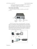
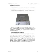
The bridge antenna port is located on the front of the 3e–525C–2. To
obtain the best performance, the bridge antenna should be placed away
from the AP antennas. Use a 1.5 meter low loss antenna cable to connect
a directional antenna to the 3e–525C–2. The maximum gain for the direc-
tional antenna should be 14 dBi.
Mounting Kit Setup
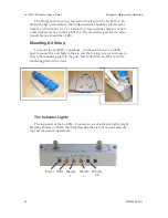
To mount the 3e–525C–2 outdoors, you should choose a suitable
post to mount the unit high in the air. Use the U-ring, screws and nuts to
attach the mounting plate to the post. Next attach the 3e–525C–2 to the
mounting plate with screws.
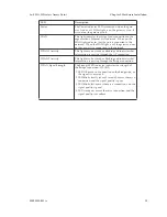
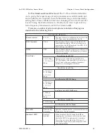
The Indicator Lights
The top panel of the 3e–525C–2 contains a set of indicator lights (Light
Emitting Diodes or LEDs) that help describe the state of various network-
ing and connection operations.
Power WAN WLAN
1
WLAN
2
WLAN
SS
Summary of Contents for AirGuard 3e-525C-2
Page 2: ...This page intentionally left blank ...
Page 3: ...3e Technologies International s AirGuard Wireless Access Point User s Guide Model 3e 525C 2 ...
Page 8: ...vi 29000155 0001 A This page intentionally left blank ...
Page 76: ...3e 525C 2 Wireless Access Point Chapter 4 Wireless Bridge Configuration 68 29000155 001 A ...

