background image

   5

Selection Charts

Selecting the Proper Nozzle Size

Follow your material suppliers recommendations for
proper nozzle size. In general, use the smaller nozzle
sizes for low flow rates or light viscosity materials and
larger nozzle sizes for higher flows and higher viscosity
materials.

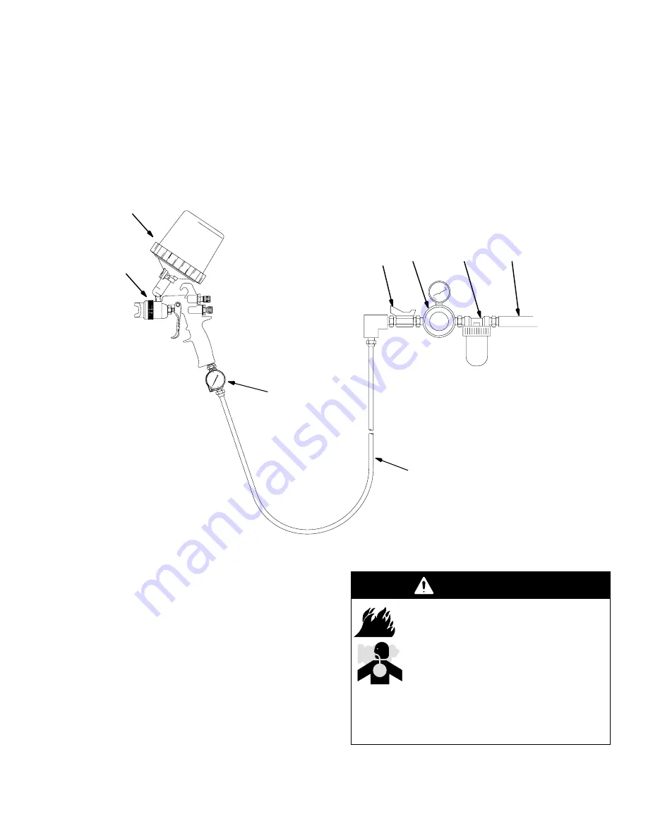
Typical Installation

KEY

A

Gun
See page 25 for gun part numbers.

B

3M PPS Cup System

C

Needle Valve Inlet; 1/4 npsm

D

Air Hose

Recommend 

5/16” (7.9 mm) ID hose

Optional 

3/8” (9.5 mm) ID hose

E

Air Shut-off Valve

F

Air Regulator

G

Air Filter

H

Air Supply Line

A

C

D

E

F

G

H

07600A

B

The spray guns were designed to produce the highest
quality finish with today’s automotive paint systems.

The HVLP and Compliant guns typically utilize 29 psi
(200 kPa, 2.0 bar) inbound air pressure to produce
high quality paint finishes and comply with environ-
mental regulations.

The air regulator must have a minimum air flow
capacity of 30 scfm at 100 psi (0.7 MPa, 7 bar) air
pressure.

Ventilate the Spray Booth

WARNING

To prevent hazardous concentrations of
toxic and/or flammable vapors, spray
only in a properly ventilated spray booth.
Do not operate the spray gun unless
ventilation fans are operating.

Check and follow all of the National,
State and Local codes regarding air ex-

haust velocity requirements.

Check and follow all local safety and fire codes.

Summary of Contents for 16212

Page 1: ...liant and Airspray 100 psi 0 7 MPa 7 bar Maximum Working Air Pressure 29 psi 200 kPa 2 0 bar Maximum Compliant Inbound Air Pressure HVLP and Compliant U S Patent Pending Table of Contents Symbols 2 Wa...

Page 2: ...ible with equipment wetted parts See Technical Data in all equipment manuals Read fluid and solvent manufacturer s warnings Check equipment daily Repair or replace worn or damaged parts immediately Do...

Page 3: ...c lamps and plastic drop cloths potential static arc Keep work area free of debris including solvent rags and gasoline Do not plug or unplug power cords or turn lights on or off when flammable fumes a...

Page 4: ...Airspray Guns Gun and PPS Cup Assy Orifice Size Pattern Length Air Cap Marking Housing Color Part No in mm in mm 16204 051 1 3 9 228 A Black 16205 055 1 4 9 228 A Black 16206 059 1 5 9 228 A Black 162...

Page 5: ...B The spray guns were designed to produce the highest quality finish with today s automotive paint systems The HVLP and Compliant guns typically utilize 29 psi 200 kPa 2 0 bar inbound air pressure to...

Page 6: ...e to the gun See Fig 3 If your regulated air source does not have a filter install an air filter G on the air line to ensure a dry clean air supply to the gun Dirt and moisture can ruin the appearance...

Page 7: ...ilm is optional 1 Weigh paint in the cup with liner according to paint manufacturers instructions before mixing product Fig 4 2 Mix product as needed 3 Take the lid with built in strainer and snap ont...

Page 8: ...line connected invert gun and pull trigger fully open NOT partially to bleed air from the liner NOTE Air only needs to be bled if spraying in the inverted position Fig 7 8 With the air removed from t...

Page 9: ...Turn the fluid adjustment knob 21 counterclock wise until no restriction of the trigger movement is felt then turn out another half turn When the knob is turned far enough the trigger should be able...

Page 10: ...in Adjusting the Spray Pattern page 9 If the red band on the knob stem 21 is visible the knob is not adjusted correctly and could result in serious injury Repeat steps in Adjusting the Spray Pattern p...

Page 11: ...he pressure stop spraying check or service any of the system equipment or install or clean the spray nozzle Pressure Relief Procedure 1 Turn off the air supply to the gun 2 Disconnect air line from th...

Page 12: ...to 200 mm from the object being sprayed See Fig 14 2 To obtain an even finish use smooth even strokes across the surface to be sprayed with 50 over lap The PPS gun cup is a sealed system and can be sp...

Page 13: ...se needle valve and gauge 30 to solvents or gauge may be damaged 02055 Do not immerse the gun in solvent Do not wipe the gun with a cloth soaked in solvent ring out the excess Do not point the gun up...

Page 14: ...cup is empty the collapsed liner and lid may be disposed Consult all local state and federal regulations or authorities for proper disposal Cleaning the gun 1 Remove the air cap retaining ring 15 and...

Page 15: ...nt for prolonged periods of time Fig 18 02011 7 To avoid galling of the fluid nozzle in the spray housing 2a apply a thin film of lubricant to the back surface of the nozzle taper where it seats and a...

Page 16: ...obstruction in fluid passage Flush with solvent Dry or loose fluid needle packing nut Lubricate or tighten Pattern is curved Air Cap or Fluid Tip Defective Determine if defect is in the Air Cap or Fl...

Page 17: ...ource and hose Fluid needle not open enough Open fluid needle more Mix is too thick for fluid tip size Change to larger size Fluid leaking dripping from PPS cup PPS cup lid loose Tighten PPS Locking C...

Page 18: ...5 N m U cup lips face towards the front of the gun 15b Parts included in Rebuild Kit 16230 Item 2 includes 2a 2b Item 13 includes item 13a Item 25 includes 25a 25d 29 28 1 2 3 4 5 6 7 8 TI3619F 1 4 2a...

Page 19: ...parts indicated in Fig 21 with lubricant 16232 This item is not included with gun Disassembling the gun 1 Relieve the pressure 2 Flush the spray gun page 6 3 Remove the air cap retaining ring 15 and...

Page 20: ...2a to plug the end Install one end of the o ring into the groove in the housing then press the rest of the o ring into place 4 Unscrew the packing screw 8 from the adapter 4 with the gun tool 28 5 Us...

Page 21: ...nut 25a Be careful not to damage the seal surface or the nut s internal threads 4 One at a time install the new u cup packings 25b with the packing installation tool 29 the u cup lips must face toward...

Page 22: ...into the back of the gun until a definite snap is felt 5 Using a mechanical pick remove the u cup packing 20 and spacer 35 from the fluid valve nut 19 Be careful not to damage the seal surface or the...

Page 23: ...17 wave washer 18 and screw 11 Torque the screw to 20 30 in lb 2 3 3 4 N m 9 To avoid galling of the fluid nozzle in the spray housing 2a apply a thin film of lubricant to the back surface of the nozz...

Page 24: ...includes 25a 25d 29 28 TI3619F 1 4 2a 2b 5 8 9 10 11 17 12 13 14 13a 15 26 16 22 20 23 19 24 25c 21 25a 25b 25d 18 30 30a 34 15b 1 1 1 1 2 3 3 3 3 5 4 6 6 7 A 35 HVLP two grooves Airspray no groove H...

Page 25: ...adjustment 1 22 SPRING air valve 1 23 SPRING needle 1 24 FITTING air inlet 1 25 PATTERN ADJUSTMENT VALVE ASSY Includes items 25a 25d 1 25a NUT pattern adjustment 1 25b U CUP 2 25c VALVE pattern adjus...

Page 26: ...sembly 234292 Cup Assembly 5 1 6 2 4 3 7 Ref No Part No Description Qty 1 COLLAR locking 1 2 LID paint cup 1 3 STRAINER 200 micron 1 Ref No Part No Description Qty 4 LINER 1 5 CUP 1 6 FILM mix ratio o...

Page 27: ...Compliant Maximum Compliant Inbound Air Pressure 29 psi 200 kPa 2 0 bar HVLP at 10 psi 70 kPa 0 7 bar max at air cap Air Consumption HVLP at 29 psi 200 kPa 2 0 bar 15 5 scfm Compliant at 29 psi 200 k...

Page 28: ...e of parts and labor will be provided by 3M and must be approved by the purchaser in advance Except as written above 3M MAKES NO OTHER WARRANTIES EXPRESS OR IMPLIED INCLUDING ANY IMPLIED WARRANTY OF M...

Reviews: