background image

20

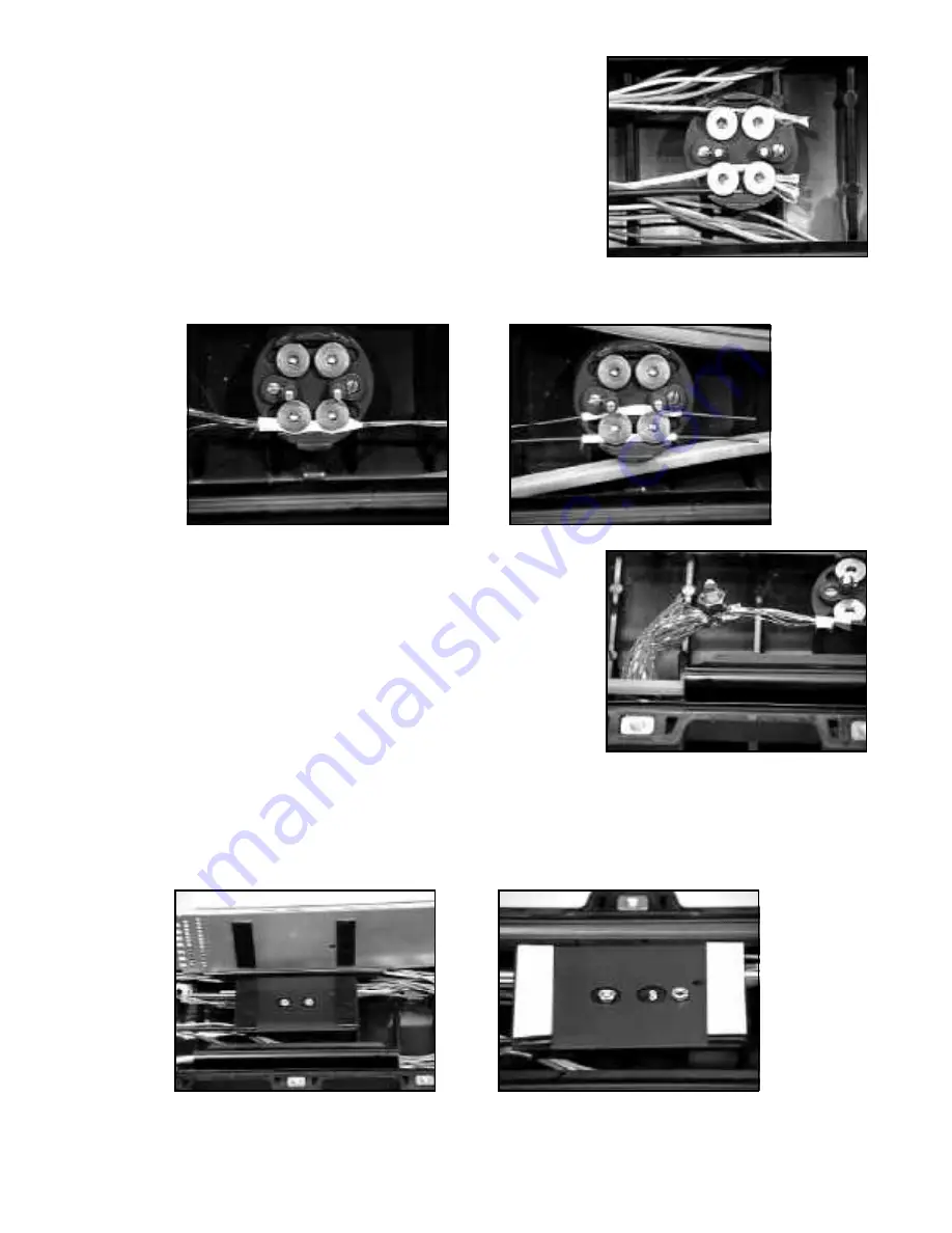
11.05 Cut and position central member under central clamp retention

screws.  If necessary, remove insulation from central member.
Using the supplied 7/32" hex key, firmly tighten each retention
screw.  If Kevlar is used for cable strain relief, wrap the Kevlar
fibers twice around one central clamp retention screw and
tighten the screw.  Cut Kevlar fibers 1/2" (13 mm) from screw.

11.06 The crossply members go under both central clamp retention screws along the outer edge.  The LXE

members go under both sides of the two screws.  Make sure the taped area is under the screws.

12.0 Universal Organizer Adapter

12.01 The universal organizer adapter is secured onto the studs located on the central clamp.  Trays that will fit on

the organizer adapter are the 3M Fibrlok Tray, AT&T, UC Series, Ditel, Preform, and Siecor.  The bottom tray
is secured to the adapter by the adhesive-backed dual-lok pads.  Additional trays are added by attaching to
the tray below or by using the supplied rod and wing nut.

AT&T Ribbon Cassette (for tray)
PNUC-RR Splice Organizer
AT&T par #103921961

11.07 A split bolt clamp is required to join the crossply members to a

number six or equivalent bond strap.  Wrap vinyl tape over the
split bolt connection to protect against sharp edges or pinch
points.  Attach to external ground stud.

Summary of Contents for 2178

Page 1: ...Instructions 2178 Fiber Optic Splice Case Issue 3 March 1992 ...

Page 2: ...ganizer Adapter 20 13 0 Splice Trays and Fiber Splicing 21 14 0 Splice Preparation 26 15 0 Splice Case Assembly 26 16 0 Racking in Building Entrances and Vaults 28 17 0 Splice Case Re entry 29 SECTION 2 2181 CABLE ADDITION KIT 30 18 0 Cable Addition Placement Preparation and Installation Butt Adapter 30 19 0 Butt Adapter 1 Installation 30 20 0 Splice Case Assembly with One Adapter 31 21 0 Cable Ad...

Page 3: ...cturer s tray size specifications on page 3 The 2180 Cable Kit is used when the 2178 Fiber Optic Splice Case is reentered All materials necessary for cable addition and splice case reassembly are included The 2181 Cable Addition Kit increases the cable entrance capacity of the 2178 Fiber Optic Splice Case One butt adapter is included in each 2181 Kit A single butt adapter allows the 2178 Splice Ca...

Page 4: ...ing Tape 1 3 03 2181 Contents Qty Spacer Assembly 1 Spacer Clamp Assembly 1 Sealing Washer Tree 2 Sealing Plugs 3 Bolts 3 5 10 Green Cable TY 1 Blue Cable TY 1 Clamp Hose 439 1 00 1 Key Hex Allen Wrench 1 Fillister Head Screws 2 Sealing Cord 1 Sealing Tape 1 3 04 2181B Contents Qty Fillister Head Screw 4 95 Screw Clamp Retention 2 Bolts 4 95 10 ...

Page 5: ...fe Tape Measure 3 10 Optional Specialized Material Required 6 AWG Ground Braid or equivalent for isolated cable shields AT T unit splitter kit for unitube fiber optic cable Spiral wrap used to protect express fibers with mid span splicing and unitube cable 1 25mm vinyl tape and 69 Glass tape for sheath isolation for crossply and LXE cable only RC 100 splice support for racking in vaults 1 2 x 2 bo...

Page 6: ... case and the components that would be required to build a new splice 2181B DOUBLE BUTT ADAPTER KIT 1 1 1 1 2181 BUTT ADAPTER KIT 1 1 1 1 2 2 2 2 3 3 3 3 2180 CABLE ADDITION KIT 1 2 2 3 4 5 5 6 7 8 8 9 10 11 2178 FIBER OPTIC SPLICE CASE 1 1 1 1 1 1 1 1 1 1 1 1 1 1 1 OF CABLES 2 3 4 5 6 7 8 9 10 11 12 13 14 15 16 ...

Page 7: ...1 2178 2181 2 2181B 1 2178 2181 2 2181B 1 2178 2181 2 2181B 1 2178 2181 2 2181B 1 2178 2181 2 2181B 1 2178 2181 2 2181B 1 BUTT SPLICE x x x x x x IN LINE SPLICE x x x x x x x OF CABLES 2 2 4 2 3 4 3 4 5 8 2 3 4 5 6 2 3 4 5 8 9 12 OF 24 FIBER TRAYS 8 8 12 8 12 8 15 12 8 15 15 12 8 OF FIBERS SPLICES 192 192 288 192 288 192 360 288 192 360 360 288 192 See cable splice kit matrix in paragraph 4 01 for...

Page 8: ...45 22 Siecor M67 070 430 12 24 24 12 18 12 12 12 12 12 12 Standard 3 46 Space Available 9 trays 8 trays 8 trays 9 trays 9 trays 11 trays 8 trays 8 trays 9 trays 15 trays 8 trays Maximum Numberof Fibrloks 108 192 192 108 162 132 96 96 108 180 96 2178 with a 2181 and No Cable 4 96 Space Available 13 trays 12 trays 12 trays 13 trays 13 trays 16 trays 11 trays 11 trays 13 trays 22 trays 11 trays Maxim...

Page 9: ... disposal instructions as given on Material Safety Data Sheet or container label for cable cleaner solvent being used 5 03 Trim any solid filler tubes and discard Trim central strength members if present to 7 178 mm from sheath openings 5 04 Scuff and center 6 152 mm of each cable as shown 5 05 Size and place washers on cable 5 06 Slide two sealing washers down each cable Use sealing washers with ...

Page 10: ... cleaner Cover all sharp edges with vinyl tape Note Carefully follow health safety and waste disposal instructions as given on the Material Safety Data Sheet or container label for cable solvent being used 6 05 Trim any solid filler tubes and discard Trim central strength members if present to 7 178 mm from sheath openings 6 06 Scuff 6 152 mm of each cable 6 07 The buffer tubes to be spliced will ...

Page 11: ... connector base 7 03 Install the connector top over the stud and tighten firmly with one of the securing nuts Place the braid over the connector stud and secure in place with the nut 7 04 If double sheath double shield fiber optic cable is being used both outer shield and inner shield need to be bonded Leave 3 4 inner sheath and 3 4 of core wrap exposed and install two shield bond connectors 180 d...

Page 12: ...strength members so the distance between collar outer edges is 4 102 mm Wrap two more layers of foam tape around outside of buffer tube s 4 102 mm 8 02 Cut two 3 4 19 mm wide by 15 381 mm long strips of foam collar tape Build a foam collar by wrapping at least two layers of foam collar tape around cable sheath 1 25 mm from the end of sheath 1 25 mm 3 4 19 mm 8 0 Core Blocking Note 1 This core bloc...

Page 13: ...ant dispensing and overwrapping steps 8 06 Overwrap with at least two additional half lapped layers of E Z wrap 8 07 Secure E Z wrap by compressing foam collar ends with three half lapped layers of highly stretched 3 4 19 mm vinyl tape 8 08 Evenly work the 4445 Sealant between buffer tube s and strength members 8 09 Overwrap entire block with one half lapped layer of highly stretched 3 4 19 mm vin...

Page 14: ...onnector flush with top nut and file sharp edges 8 17 Cut two 3 4 19 mm wide by 15 381 mm long strips of foam collar tape Starting 1 25 mm behind shield bond connector build foam collar with the foam collar tape build collar high enough to accommodate the shield bond connector bonding straps and nuts 1 25 mm 3 4 19 mm 8 11 Overwrap with one additional half lapped layer of vinyl tape 8 12 Repeat st...

Page 15: ... collars 8 20 Cut corner of 4445 Sealant bag Starting at opposite end force sealant out and fill area between foam collars Note Carefully follow health safety and disposal instructions as given on Material Safety Data Sheet or product label for 4445 Sealant Note Protective gloves should be worn during sealant dispensing and overwrapping steps 8 21 Overwrap with at least two additional half lapped ...

Page 16: ... 8 26 until all cables are blocked 8 28 Secure the cables to the splice case per the splice case practice 9 0 Sealing Washer Installation 9 01 Wrap each cable with two wraps of 2 wide DR Tape Place wraps behind foam tape collar from core block 9 02 Place the first sealing washer against the DR Tape Build cable entrance seals by wrapping 1 1 2 38 mm sealing tape between washers Wrap each cable unti...

Page 17: ...lice case Install one large green cable tie on the C O Cable and trim Install one large blue cable tie on the Field Cable and trim 10 02 Place ground stud protector cap on ground studs 10 03 If separate external grounding is not required bond across splice to either ground stud 10 0 Grounding for Shielded Cable 10 01 Remove ground stud protectors If bonding to central clamp is not required remove ...

Page 18: ... required to assure ground isolation from the central clamp c The final crossply and LXE member length should extend 3 76 mm beyond the central clamp d Starting 3 76 mm from the final cut end wrap two strips 2 51 mm long of 1 25mm wide vinyl tape lengthwise around the crossply members Make sure the tape is overlapped and no metal is exposed Each LXE member requires only one piece of vinyl tape e W...

Page 19: ...r tubes or ribbon cable Note Spiral wrap or equivalent must be applied to unitube cable before applying cable tie 11 03 Coil buffer tube ribbon unitube or fibers bundles inside splice case base If using a splice tray that allows fiber entry at all four corners or two corners in the same end the last 3 4 loop will allow tray movement for splicing away from splice case Coils should be full splice ca...

Page 20: ...a is under the screws 12 0 Universal Organizer Adapter 12 01 The universal organizer adapter is secured onto the studs located on the central clamp Trays that will fit on the organizer adapter are the 3M Fibrlok Tray AT T UC Series Ditel Preform and Siecor The bottom tray is secured to the adapter by the adhesive backed dual lok pads Additional trays are added by attaching to the tray below or by ...

Page 21: ... cables to be spliced per the company practice to expose 8 feet 2 4 m of cable buffer tubes Clean the sealant from buffer tube s per company practice Note Carefully follow health and safety information given on cleaning solvent container label or Material Safety Data Sheet 13 04 If the cable is a ribbon unitube or slotted core loose tubes from a unit splitter kit will be placed over the fibers to ...

Page 22: ...ced into a tube 13 11 Slide the segment of tubing over the buffer tube about 1 25 mm and secure with two wraps of vinyl tape 13 12 Mount the universal organizer adapter in the splice case base 13 13 Cut the Dual Lok to fit the four flat pads on the tray bottom Remove protective liner and adhere 13 14 Center the tray over the adapter and press down to secure ...

Page 23: ...Press the buffer tube into the channel to secure The buffer tube should stop within 1 4 6 mm of the channel end 13 19 Lay at least one complete loop of fiber from the first buffer tube on the tray with the fiber ends crossing the front CUT HERE mark 13 20 Now cut the fiber ends at the mark Be sure to cut ONLY the fiber ends 13 21 Remove the cut fibers from the tray but leave the buffer tube instal...

Page 24: ... but leave the buffer tube installed 13 26 For remaining buffer tubes repeat steps 13 15 through 13 25 13 27 Store the first two fibers to be spliced under the tray tabs 13 28 Remove the minimum length of fiber required to prepare and split the fibers 13 29 Place the splicing tool in close proximity to the splice tray Prepare and splice the first pair of fibers Note If fusion splicing method is us...

Page 25: ...3 31 Prior to placing the splice into the pocket observe how the splice lays in its relaxed state Rotate the splice through the smallest possible angle Snap splice into pocket cap side down 13 32 For remaining fibers repeat steps 13 27 through 13 31 Fill pockets in order 13 33 Install and close tray cover making sure that all fibers are properly stored under the tray tabs 13 35 Slide the post of t...

Page 26: ...entire stack between the front snaps and the cover snaps is recommended This allows for reinforcement before sealing splice case 13 40 The label on the top of the tray cover allows for the identification of splices and or fiber count 15 0 Splice Case Assembly 15 01 Seal splice case walls a Lay sealing cord into channel along both sides of the splice case base Do not stretch sealing cord 14 0 Splic...

Page 27: ...c Press seal plugs into each vacant cable entrance port 15 03 Set splice case cover directly on top of the splice case base 15 04 Turn all bolts until they have been threaded several complete turns into the nut inserts or until the cover rests on top of the sealing cord 15 05 Tighten all bolts in numbered sequence A torque wrench is not needed If a torque wrench is used do not exceed 20 Ft Lbs 240...

Page 28: ...ng e Tighten bolts to prevent movement 16 02 Horizontal Racking a Determine height of splice b Use RC 100 splice support clips Note Follow instructions provided with packaging of RC 100 clips c Insert clips in racking or unistrut d Insert a standard manhole rack through the brackets e Use 2 51 mm bolts to secure 2178 to installed rack f Tighten bolts to prevent movement 16 03 Fire Retardant Backbo...

Page 29: ...embled all sealant must be removed and cable entrance port seals reconstructed a Remove old sealing cord from splice case channels This is accomplished by pressing a small amount of sealant into the channel and removed with a quick snap The quick action will remove the old sealant This is done to the cover and base Note Do cleaning immediately after prying the splice case apart b Plug removal inse...

Page 30: ...ntral clamp to the splice case base 18 02 Cable preparation See Section 5 0 18 03 Stack Central Clamps b Place the second level central clamp directly on top of splice case base central clamp and secure the two fillister head screws supplied with the 2181 kit 18 04 Bonding for Shielded Cable See Section 7 0 18 05 Core Blocking See Section 8 0 18 06 Grounding for Shielded Cable See Section 10 0 18 ...

Page 31: ...lf to fill the channel c Press seal plugs into each vacant cable entrance port 20 03 Set butt adapter 1 flange side down as is on top of splice case base Note These steps are done to seat cord between splice case and butt adapter 20 04 Set cover directly over butt adapter 1 20 02 Seal plug construction a Select a plug for each vacant cable entrance port b Wrap each plug three times with 1 1 2 38 m...

Page 32: ...4 95 126 mm bolts supplied with the 2181B kit 21 02 Cables should be placed in cable entrance port in a butt configuration for easier storage 21 03 Cable preparation See Section 5 0 21 04 Stack Central Clamps Note Buffer tube retainers may be removed for installation of central clamp and additional trays Replace buffer tube retainers after clamp and trays are installed a Remove the splice trays fr...

Page 33: ...ealing cord b Lay two strips of sealing cord 1 1 2 38 mm in length between the cable entrance ports on each end of the splice case base or one 3 76 mm length folded in half to fill the channel 23 02 Seal plug construction a Select a plug for each vacant cable entrance port b Wrap each plug three times with 1 1 2 38 mm sealing tape Sealing tape OD should be flush with plug OD Both ends of tape shou...

Page 34: ...r five minutes retighten all bolts on the splice case 23 08 Flash test splice case with 10 psi maximum 24 03 Beginning with any corner screw in bolt until the splice case cover has been pried from butt adapter about 1 4 6 mm Repeat with the other bolt on same end of the splice case 24 04 Follow same procedure with the bolts on opposite end of the splice case 24 05 Repeat steps 27 03 and 27 04 unti...

Page 35: ...f the butt adapter The threaded corner inserts are located directly beneath the previously removed corner inserts 24 08 For the SINGLE BUTT adapter splice case repeat steps 27 03 through 27 05 to separate butt adapter 1 from splice case base 24 09 For DOUBLE BUTT adapter splice case repeat steps 27 06 through 27 08 to separate butt adapter 2 from butt adapter 1 Note If splice case is to be reassem...

Page 36: ...mendations of the Seller which are not contained in the Seller s current publications shall have no force or effect unless contained in an agreement signed by an authorized officer of the Seller The statements contained herein are made in lieu of all warranties express or implied including but not limited to the implied warranties of merchantability and fitness for a particular purpose which warra...

Reviews: