26
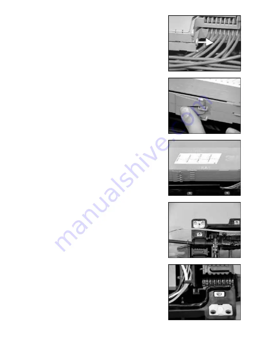
13.36 Now slide the tray laterally (flexing the lever arm outward) enough
to allow the post to be inserted into the opposite lever arm hole.
(Back view shown).
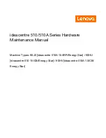
13.37 Lift the tray being added upwards approximately 1/2" (13 mm).
Push in on the front snap of the installed tray and lower new tray
down and over the snap.
13.38 For additional trays, repeat steps 13.35 through 13.37.
13.39 If trays are used in an aerial application, a wrap of vinyl tape
around entire stack between the front snaps and the cover snaps
is recommended. This allows for reinforcement before sealing
splice case.
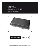
13.40 The label on the top of the tray cover allows for the identification
of splices and/or fiber count.
15.0 Splice Case Assembly
15.01 Seal splice case walls:
a. Lay sealing cord into channel along both sides of the splice
case base. Do not stretch sealing cord.
14.0 Splice Preparation
14.01 Open buffer tubes 1" (25 mm) from end of splice case base,
exposing 40" (1.02 m) of bare fiber. Protect fibers from damage.
Note:
Do not withdraw primary tubes coiled inside splice case
base.
14.02 Clean all cable grease from exposed fibers.


