background image

North American - ENG

Date Released:

05-22-18

3M-Matic

 Accuglide 4 - 2 and 3 Inch Taping Head - Type 11800                                                              

Page 14
44-0009-2146-8 / ECO# 0078045

Alignment

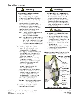
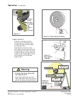
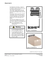
Figure 5-1   Tape Alignment

Figure 5-2  Tape Alignment

(adjustments 

continued

 on next page.)

Adjustments  

Tape Alignment and Tracking

 – 

Figure 5-1

An adjustment system behind the tape roll hub 

is provided to center the tape as it 

moves along the tape applicator rollers and 

onto the case.  Adjusting the position of the 

hub brake o

ff

 sets the tape moving through the 

applicator. 
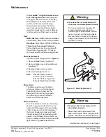
To adjust tape tracking, loosen the nut behind 

the hub brake.  Turn the screw clockwise to 

push out the hub brake, or counter-clockwise 

to move the hub brake closer to support arm.  

Retighten the nut to lock assembly in new 

position.
The tape should be applied directly over the 

center line of the case 

fl

 aps and should not 

extend past the edge of the rollers 

(Figure 5-2).

Note:

 Only 

fi

 ne adjustments for tape 


  alignment should be done on the 


  tape applicator.  

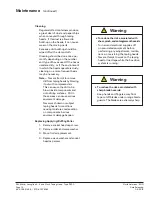
•  To reduce the risk associated with shear,
  pinch, and entanglement hazards

 -  Turn air and electrical supplies o

ff


     on associated equipment before 

  performing any adjustments, mainte-
  nance, or servicing the taping heads
-  Never attempt to work on the taping 

   head or load tape while the box drive 

   system is running.

     Warning

 Adjustment

 Nut

Summary of Contents for 3-M Matic Accuglide 4

Page 1: ...PMENT Read understand and follow all safety and operating instructions Spare Parts It is recommended you immediately order the spare parts listed in the Spare Parts Service Information section These parts are expected to wear through normal use and should be kept on hand to minimize production delays 3M Matic Accuglide 4 High Performance Taping Heads 2 and 3 Inch Type 11800 Serial For reference re...

Page 2: ...North American ENG Date Released 05 22 18 3M Matic Accuglide 4 2 and 3 Inch Taping Head Type 11800 Page ii 44 0009 2146 8 ECO 0078045 ...

Page 3: ...dentification Plate For Commercial Use Only Technical Assistance Replacement Parts and Additional Manuals For technical assistance contact our help line at 1 800 328 1390 Provide the customer support coordinatorwith the model machine name machine type and serial number that are located on the identification plate Forexample Model Accuglide 4 2 3 inch Taping Head Type 11800 Serial Number13282 To or...

Page 4: ...North American ENG Date Released 05 22 18 3M Matic Accuglide 4 2 and 3 Inch Taping Head Type 11800 Page iv 44 0009 2146 8 ECO 0078045 ...

Page 5: ...e Scotch equipment you ordered It has been set up and tested in the factory with Scotch tapes Included with each machine is an Instructions Manual Order parts by part number part description and quantity required Also when ordering parts or additional manuals include model machine name machine type and serial number that are located on the identification plate Service replacement parts and additio...

Page 6: ...North American ENG Date Released 05 22 18 3M Matic Accuglide 4 2 and 3 Inch Taping Head Type 11800 Page vi 44 0009 2146 8 ECO 0078045 ...

Page 7: ...se Manual 3 Important Safeguards 4 5 Specifications 6 7 Dimensional Drawing 7 Installation 8 Receiving and Handling 8 Installation Guidelines 8 Tape Leg Length 8 Tape Width Adjustment 8 Operation 9 11 Taping Head Components 9 Tape Loading Upper Taping Head 10 11 Tape Loading Lower Taping Head Maintenance 12 13 Tools 12 Blade Replacement 12 Blade Guard 12 Cleaning 13 Adjustments 14 15 Tape Alignmen...

Page 8: ...hall be given to 3M solely through the 3M Matic Help line 800 328 1390 To be entitled to repair or replacement as provided under this warranty the part must be returned as directed by 3M to its factory or other authorized service station designated by 3M If 3M is unable to repair or replace the part within a reasonable time after receipt thereof 3M at its option will replace the equipment or refun...

Page 9: ...e sensitive film box sealing tape to the top and or bottom center seam of regular slotted containers The compact size and simplicity of the taping head also makes it suitable for mounting in box conveying systems other than 3M Matic case sealers This includes replacement of other types of taping gluing or stapling heads in existing case sealing machines The AccuGlide 4 High Performance Taping Head...

Page 10: ...North American ENG Date Released 05 22 18 3M Matic Accuglide 4 2 and 3 Inch Taping Head Type 11800 Page 2 44 0009 2146 8 ECO 0078045 ...

Page 11: ...information contained herein is intended to enable the equipment to be maintained in perfect condition and operated safely Ensure that the manual is available to all operators of this equipment and the manual is kept up to date with all subsequent amendments Should the equipment be sold or disposed of please ensure that the manual is passed on with the machine Keep the manual in a clean and dry pl...

Page 12: ...perating or servicing the case sealer Allow only properly trained and qualified personnel to operate and or service this equipment Caution To reduce the risk associated with muscle strain Use proper body mechanics when removing or installing taping heads that are moderately heavy or may be considered awkward to lift To reduce the risk associated with impact hazards Place the taping head on a smoot...

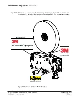
Page 13: ...ement Labels 3M Part Numbers Important Safeguards continued Important In the event the following safety labels are damaged or destroyed they must be replaced to ensure operator safety See Replacement Parts Illustrations and Parts Lists for label part numbers 34 8720 2918 5 34 8720 2917 7 3MTM AccuGlideTM TapingHead 78 0025 0308 0 CAUTION Sharp Knife ...

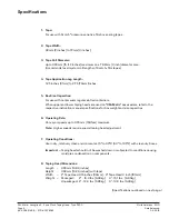
Page 14: ...tted containers When upper and lower taping heads are used on 3M Matic case sealers refer to the respective instruction manual specifications for box weight and size capacities 6 Operating Rate Conveyor speeds up to 0 76m s 150fpm maximum Note Higher speeds require special taping head adjustment 7 Operating Conditions Use in dry relatively clean environments at 5 to 40 C 40 to 105 F with clean dry...

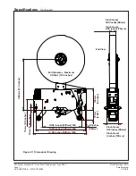
Page 15: ...ued End View Roll Diameter Maximum 390mm 15 5 Inches 10 95 Inches 278mm M6 1 42 Inches 36mm 13 78 Inches 350mm M6 14 96 Inches 380mm M6 363mm 14 3 Inches 74mm 2 9 Inches 72mm 2 83 153mm 6 inches 2 inch Head 1 89 inches 48mm 3 inch Head 2 84 inches 72mm 2 inch Head 3 15 inches 80mm 3 inch Head 4 inches 101mm 16mm 0 63 Inches Figure 2 1 Dimensional Drawing ...

Page 16: ... 2 1 4 Turn lock lever away from locking position Remove spent core Reload with a new roll make sure the adhesive side of tape faces toward incoming cartons Return lock lever to secure position after reloading tape Also check and make sure the spring lock was not bent during this process Note Make sure lock lever is in correct position during and after loading Pushing or pulling a roll of tape whi...

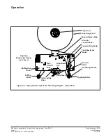
Page 17: ...Drum Tape Supply Roll Tape Adhesive Side Tension Wrap Roller Knurled Roller Tab Adjustment Roller Threading Needle Applying Roller One Way Tension Roller Applying Mechanism Spring not shown Buffing Arm Cover Buffing Roller Figure 3 1 Taping Head Components Threading Diagram Upper Head Knife Guard Tape Cut Off Knife Adjustment Bar Intermediate Wipe ...

Page 18: ...nsion wrap roller Position 1 then around one way tension roller Position 2 4 Pull it over knurled roller so adhesive side is in contact with this roller Position 3 5 Pull tape down over tab adjustment roller Pull it under knurled roller and between crescent tape guide and support pad Position 4 The tape should extend 13mm past the applying compression roller 6 Cut away any excess tape Important Do...

Page 19: ...o create slack tape while pulling tape through tape applying mechanism until tape is through and tape is in alignment with applying roller Excess tape can be cut with a scissors at 1 2 inch past the applying roller To reduce the risk associated with sharp blade hazards Keep hands and fingers away from tape cutoff blades under orange blade guards The blades are extremely sharp Warning Crescent Tape...

Page 20: ...ew Note Check the blade position to insure proper clearance between blade and guard by slowlypivoting blade guard back Blade Guard The blade guard covers the blade whenever a box is not being taped Periodically check to be sure the blade guard is functioning properly and returning to cover the blade Replace any defective parts Blade Grease Pad To reduce adhesive build up the taping heads are equip...

Page 21: ...essed air This can cause the dirt to be blown inside components and onto sliding surfaces Dirt in these areas can cause serious equipment damage Never wash down or subject taping heads to conditions causing moisture condensation on components Serious equipment damage happen Replacing Applying Buffing Roller 1 Remove socket head cap screw 2 Remove roller and wave washer 3 Mount roller replacement 4...

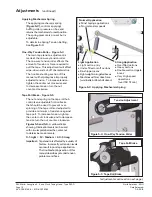
Page 22: ...sen the nut behind the hub brake Turn the screw clockwise to push out the hub brake or counter clockwise to move the hub brake closer to support arm Retighten the nut to lock assembly in new position The tape should be applied directly over the center line of the case flaps and should not extend past the edge of the rollers Figure 5 2 Note Only fine adjustments for tape alignment should be done on...

Page 23: ... should be used to prevent over spinning of the tape roll and adjusted to provide a minimum of resistance against tape pull To increase tension tighten the center nut clockwise and to decrease tension turn the nut counter clockwise Figures 5 5 and 5 6 Ayellow sticker showing 3 indication levels can be used with circular plate below the center nut to determine tension levels 0 1 Light 1 2 Medium 2 ...

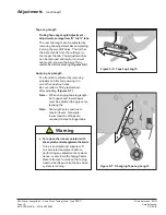
Page 24: ...t tab is adjusted by removing adjustment roller and securing it in one of five position holes Be sure roller is firmly reattached after adjusting Figures 5 7 Note When changing tape leg length both upper and lower heads must be adjusted to apply same leg lengths Note Tab lengths are sensitive to tension levels Generally lower tension settings are required to create longer tabs To reduce the risk a...

Page 25: ...up between the knurled roller and its shaft Clean and lubricate shaft Remove all lubricant from roller surfaces Adjust the tape web alignments Readjust the machine s center alignment setting Check the position of the tab adjustment roller and adjustment bar Re adjust sealer so bottom of taping head is from top surface of carton Clean and adjust Grease blade grease pad replace the blade Increase de...

Page 26: ...he one way tension roller is defective The tape roll not correctly aligned The tape applicator off center Centering guides not centered Box flaps not of equal length Correction Adjust the one way tension roller and or the tape drum assembly or tighten loosen hub adjust nut Clean adhesive deposits from the surface ends and shafts ofthe rollers Then lubricate roller shafts Remove all lubricant from ...

Page 27: ...on where taping head is mounted Contact your 3M provider for more information AccuGlide 4 High Performance 3 Inch Taping Heads Qty Part Number Description 1 78 0025 0325 4 Blade 1 78 0025 0252 0 Spring Kit 1 78 0025 0251 2 Spare Parts Kit 1 78 0025 0254 6 Spare Wiper Kit 1 78 0025 0303 1 Roller Kit Plasma Coated 1 78 0025 0305 6 Knife Retract Kit 1 78 0025 0272 8 Spring Lower Tape Head 4 78 0025 0...

Page 28: ...North American ENG Date Released 05 22 18 3M Matic Accuglide 4 2 and 3 Inch Taping Head Type 11800 Page 20 44 0009 2146 8 ECO 0078045 ...

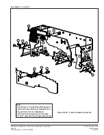
Page 29: ... Figure 11806 Blade Arm Assembly Figure 11802 Cut Off Bracket Cylinder Assembly Figure 11802 Frame Hardware Tape Head AccuGlide 4 2 and 3 inch Figure 11801 Full Assembly Figure 11803 Core Mechanism Assembly Figure 11809 Clutch Roller Assembly Figure 11804 Front Roller Arm Assembly Figure 118 Rear Roller Arm Assembly Figure 11808 Tape Roll Mast Assembly ...

Page 30: ...009 2146 8 ECO 0078045 AccuGlide 4 2 and 3 Figure 11801 Full Assembly 12 2 10 8 3 7 6 9 10 1 10 1 11 5 4 Note View Shown is for Right Hand Taping Head Left Hand View is Mirrored Opposite View Also see Parts List for all Right and Left Hand View Information and for both 2 and 3 and Little David Taping Head Parts ...

Page 31: ...ly 3 11801 3 78 0025 0310 6 Cutting Assembly 2 Full Blade RH 78 0025 0311 4 Cutting Assembly 2 Full Blade LH 78 0025 0312 2 Cutting Assembly 3 Full Blade RH 11801 4 78 0025 0326 2 Stud 14 5mm Mounting 78 0025 0327 0 Stud 25mm Mounting 11801 5 78 0025 0422 9 Spacer 4 7mm 11801 6 78 0025 0425 2 Washer 11801 7 78 0025 0424 5 Shaft 12 70 x 31 0 11801 8 78 0025 0423 7 Washer Stainless Steel 11801 9 78 ...

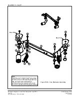
Page 32: ...045 AccuGlide 4 2 and 3 Figure 11802 Frame Hardware Assembly 11 6 5 19 8 3 8 18 11 10 13 9 18 7 2 17 5 18 14 4 15 12 7 16 1 Note View Shown is for Right Hand Taping Head Left Hand View is Mirrored Opposite View Also see Parts List for all Right and Left Hand View Information and for both 2 and 3 and Little David Taping Head Parts ...

Page 33: ...e Clamp 78 0025 0463 3 Plate Clamp LD 2 78 0025 0455 9 Plate Clamp LD 3 11802 6 78 0025 0428 6 Plate Skip 11802 7 78 0025 0431 0 Nut Stop 78 0025 0484 9 Nut Stop LD 11802 8 78 0025 0426 0 Wiper Clamping Plate 11802 9 78 0025 0430 2 Pin Anchor 11802 10 78 0025 0429 4 Pin Stop 11802 11 78 0025 0315 5 PU Stop 78 0025 0315 5 PU Stop LD 11802 12 34 8720 2917 7 Label 11802 13 78 0025 0432 8 Stop 11802 1...

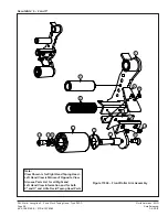
Page 34: ...O 0078045 AccuGlide 4 2 and 3 Figure 11803 Core Mechanism Assembly Base Plate Base Plate 6 9 12 10 4 2 5 3 1 11 8 7 13 Note View Shown is for Right Hand Taping Head Left Hand View is Mirrored Opposite View Also see Parts List for all Right and Left Hand View Information and for both 2 and 3 and Little David Taping Head Parts ...

Page 35: ...0025 0284 3 Roller Arm Assembly Rear 2 RH 78 0025 0516 8 Roller Arm Assembly Rear 2 LH STD 78 0025 0290 0 Roller Arm Assembly Rear 2 RH LD 78 0025 0294 2 Roller Arm Assembly Rear 3 RH 78 0025 0300 7 Roller Arm Assembly Rear 3 RH LD 11803 3 78 0025 0424 5 Shaft 12 70 x 31 0 11803 4 78 0025 0423 7 Washer Stainless Steel 11803 5 78 0025 0425 2 Washer 11803 6 78 0025 0277 7 Push Bar molded 11803 7 78 ...

Page 36: ...46 8 ECO 0078045 AccuGlide 4 2 and 3 Figure 11804 Front Roller Arm Assembly 7 8 3 2 10 12 13 4 1 9 11 5 15 6 14 Note View Shown is for Right Hand Taping Head Left Hand View is Mirrored Opposite View Also see Parts List for all Right and Left Hand View Information and for both 2 and 3 and Little David Taping Head Parts ...

Page 37: ...nurled 3 11804 3 78 0025 0287 6 Roller Assembly 57mm 78 0025 0296 7 Roller Assembly 77mm 11804 4 78 0025 0278 5 Roller Spiral 2 78 0025 0279 3 Roller Spiral 3 11804 5 78 0025 0253 8 Guide Tape Pre Form 2 78 0025 0254 6 Guide Tape Pre Form 3 11804 6 78 0025 0254 6 Support Tape 11804 7 78 0025 0280 1 Washer Drag 11804 8 78 0025 0459 1 Shaft 2 78 0025 0436 9 Shaft 3 11804 9 78 0025 0460 9 Clamp 2 78 ...

Page 38: ...44 0009 2146 8 ECO 0078045 AccuGlide 4 2 and 3 Figure 11805 Rear Roller Arm Assembly 2 4 5 3 8 7 6 1 Note View Shown is for Right Hand Taping Head Left Hand View is Mirrored Opposite View Also see Parts List for all Right and Left Hand View Information and for both 2 and 3 and Little David Taping Head Parts ...

Page 39: ... 0025 0438 5 Roller Arm Rear RH 78 0025 0468 2 Roller Arm Rear LH 78 0025 0457 5 Roller Arm Rear RH LD 11805 2 78 0025 0459 1 Shaft 2 78 0025 0436 9 Shaft 3 11805 3 78 0025 0278 5 Roller Spiral 2 78 0025 0279 3 Roller Spiral 3 11805 4 78 0025 0280 1 Washer Drag 11805 5 26 1001 9843 7 Screw M6 x 16 Flat Socket Head 11805 6 78 8010 7209 7 Screw M6 x 12 Socket Cap 11805 7 78 0025 0508 5 Washer M6 Loc...

Page 40: ...4 0009 2146 8 ECO 0078045 AccuGlide 4 2 and 3 Figure 11806 Blade Arm Assembly Note View Shown is for Right Hand Taping Head Left Hand View is Mirrored Opposite View Also see Parts List for all Right and Left Hand View Information and for both 2 and 3 and Little David Taping Head Parts 8 2 10 5 11 4 1 9 3 7 8 ...

Page 41: ...Guard Assembly Blade 2 RH 78 0025 0410 4 Guard Assembly Blade 3 RH 11806 3 78 0025 0440 1 Bar Adjusting 11806 4 78 0025 0441 9 Pin Anchor 11806 5 78 0025 0320 5 Blade 2 78 0025 0325 4 Blade 3 11806 6 78 0025 0319 7 Plate Cutting Guide 3 78 0025 0476 5 Plate Cutting Guide 3 11806 7 78 0025 0481 5 Screw M5 X 8 HSBHCS 11806 8 78 0025 0510 1 Screw M5x12 Set 11806 9 78 0025 0396 5 Screw M4 X 8 Socket C...

Page 42: ...5 22 18 3M Matic Accuglide 4 2 and 3 Inch Taping Head Type 11800 Page 34 44 0009 2146 8 ECO 0078045 7000r 7000r3 HS Pro 4 2 1 Figure 11807 Cut Off Bracket Cylinder Assembly Reverse View Shown for Clarity 3 6 14 7 5 8 9 11 10 13 12 15 16 ...

Page 43: ... 8 Disk Assembly TAM 5 Slot 11807 3 78 0025 0496 3 Cylinder 3 4 B x 0 75 Spring Return 11807 4 78 0025 0479 9 Washer M7 Flat 11807 5 78 0025 0497 1 Bumper 1 4 28 Female Round 11807 6 78 0025 0499 7 Fitting 6mm x 1 8 90 Elbow Male NPT 11807 7 78 0025 0498 9 Nut 1 4 28 Hex Jam PLT 11807 8 78 8137 8500 9 Quick Disconnect 6mm Air Male Tube 11807 9 78 0025 0500 2 Control 6mm Flow Union 11807 10 78 8052...

Page 44: ...045 AccuGlide 4 2 and 3 Figure 11808 Tape Roll Mast Assembly 2 HUB ASSY 50385 2 HUB ASSY 50385 8 7 4 1 11 2 6 3 9 10 5 12 13 Note View Shown is for Right Hand Taping Head Left Hand View is Mirrored Opposite View Also see Parts List for all Right and Left Hand View Information and for both 2 and 3 and Little David Taping Head Parts ...

Page 45: ...Spring Conical Hub 11808 4 78 0025 0285 0 Hub Tape Roller 2 78 0025 0295 9 Hub Tape Roller 3 11808 5 78 0025 0448 4 Lever Lock RH 78 0025 0470 8 Lever Lock RH 11808 6 78 0025 0449 2 Washer Friction 11808 7 78 0025 0451 8 Plate Fixed Spring 11808 8 78 0025 0452 6 Spring Lock 11808 9 78 0025 0453 4 Plate Tension Gauge 11808 10 78 0025 0504 4 Nut Nylock M6 x 1 0 11808 11 78 0025 0454 2 Nut Jam 5 8 15...

Page 46: ...O 0078045 AccuGlide 4 2 and 3 Figure 11809 Clutch Roller Head Press Fit Bearing RH LH Reverse Direction 5 6 2 7 3 1 4 Note View Shown is for Right Hand Taping Head Left Hand View is Mirrored Opposite View Also see Parts List for all Right and Left Hand View Information and for both 2 and 3 and Little David Taping Head Parts ...

Page 47: ...809 1 78 0025 0461 7 Shaft One Way Clutch Roller 2 78 0025 0443 5 Shaft One Way Clutch Roller 3 11809 2 78 0025 0276 9 Spring Conical Clutch 11809 3 78 0025 0306 4 Roller Clutch 2 RH 78 0025 0316 3 Roller Clutch 2 LH 78 0025 0307 2 Roller Clutch 3 RH 11809 4 78 0025 0444 3 Spacer Clutch Roller 11809 5 78 0025 0504 4 Nut Nylock M6 x 1 0 11809 6 78 0025 0445 0 Plate Tension Gauge 11809 7 78 0025 044...

Page 48: ...North American ENG Date Released 05 22 18 3M Matic Accuglide 4 2 and 3 Inch Taping Head Type 11800 Page 40 44 0009 2146 8 ECO 0078045 ...

Page 49: ...North American ENG Date Released 05 22 18 3M Matic Accuglide 4 2 and 3 Inch Taping Head Type 11800 Page 41 44 0009 2146 8 ECO 0078045 ...

Page 50: ...North American ENG Date Released 05 22 18 3M Matic Accuglide 4 2 and 3 Inch Taping Head Type 11800 Page 42 44 0009 2146 8 ECO 0078045 ...

Reviews: