


3M Instruction Guide: 3M
TM
Locator Plate 3443-81-XX, 3D-Printed
P a g e
4 | 8
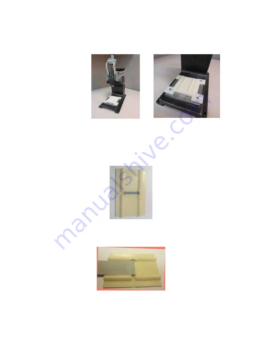
3.5
Install the 3M
TM
base plate, and appropriate locator plate insert on the press.
(See Figure 5) Add platen by positioning it parallel with the connector body and
cover. (See Figure 9)
Figure 5
4.0
Procedures for Cable Preparation
Before assembly of the connector can take plate, the cable must be prepared.
4.1
Place the cover into the locator plate. (See Figure 6)
Figure 6
4.2
Place the properly sized ribbon cable into the cover in the locator plate. (See
Figure 7)
Figure 7


