background image

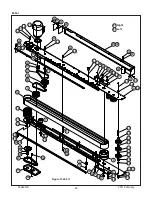
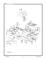
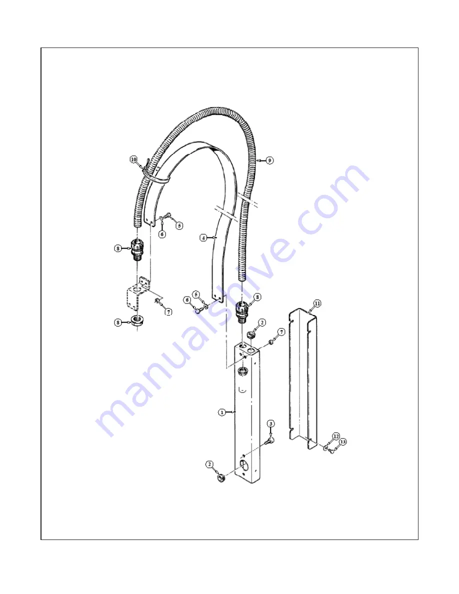
Figure 6166

 800at

2011 February

800at-NA 

Summary of Contents for 39600

Page 1: ...ENT Read understand and follow all safety and operating instructions It is recommended you immediately order the spare parts listed in the Spare Parts Service Information section These parts are expected to wear through normal use and should be kept on hand to minimize production delays 3M Industrial Adhesives and Tapes 3M Center Building 220 5E 06 St Paul MN 55144 1000 Instructions and Parts List...

Page 2: ...eshooting repair work and servicing plus parts list of the 3M Matic TM 800at NA Adjustable case sealer 3M Industrial Adhesives and Tapes 3M Center Building 220 5E 06 St Paul MN 55144 1000 Edition February 2011 Copyright 3M 2011 All rights reserved The manufacturer reserves the right to change the product at any time without notice 2011 February 800at NA ...

Page 3: ...sted below Included with each machine is an Instructions and Parts List manual Technical Assistance Replacement Parts and Additional Manuals Contact your local service provider Provide the customer support coordinator with the model machine name machine type and serial number that are located on the identification plate For example Model 800at Type 39600 Serial Number 13282 Minimum billing on part...

Page 4: ...THIS PAGE IS BLANK ...

Page 5: ...actory with Scotch tapes If any problems occur when operating this equipment and you desire a service call or phone consultation call write or fax the appropriate number listed below Included with each machine is an Instructions and Parts List manual SERVICE REPLACEMENT PARTS AND ADDITIONAL MANUALS AVAILABLE DIRECT FROM Order parts by part number part description and quantity required Also when or...

Page 6: ...THIS PAGE IS BLANK ...

Page 7: ...formation 5 3 2 Signal Words Explanation 5 3 3 Table of Warnings 6 7 3 4 Operator s Qualifications Definition 8 3 5 Number of Operators 8 3 6 Safe Use of the Machine Instructions 8 3 7 Residual Hazards 8 3 8 Prevent Other Hazards Recommendations and Measures 8 3 9 Personal Safety Measures 8 3 10 Incorrect Predictable Actions Not Allowed 8 3 11 Operator s Required Skill Levels 9 3 12 Component Loca...

Page 8: ...8 THIS PAGE IS BLANK ...

Page 9: ...Outboard Tape Roll Holder 19 7 9 Preliminary Electric Inspection 19 7 10 Main Power Machine Connection and Inspection 19 7 11 Phases Inspection 19 8 Theory of Operation 8 1 Working Cycle Description 20 8 2 Running Mode Definition 20 8 3 1 Normal Stop Procedure 20 8 3 2 Emergency Stop 20 9 Controls 9 1 Box Width Adjusting Knobs 21 9 2 Box Height Adjusting Crank 21 9 3 Start Stop Main Switch 21 9 4 ...

Page 10: ...THIS PAGE IS BLANK ...

Page 11: ...lade Cleaning 26 13 8 Drive Belt Replacement 27 29 13 9 Drive Pulley Ring 28 13 10 Drive Belt Tension 29 13 11 Special Set Up Procedures 29 35 13 11 1 Case Sealer Frame 29 13 11 2 Taping Heads 30 31 13 11 3 Drive Belt Assembly Height 31 13 11 4 Box Height Range Outer Column Repositioning 32 35 13 12 Maintenance Work Log 37 14 Additional Instructions 14 1 Machine Disposal Information 39 14 2 Fire e...

Page 12: ...l MN 55144 1000 Drw drawing Ex for example Fig exploded view figure no spare parts Figure Illustration Max maximum Min minimum Nr number N A not applicable OFF machine not operating ON machine operating PLC Programmable Logic Control PP Polypropylene PTFE Polytetraflourethelene PU PU Foam Polyurethane Foam PVC Poly vinyl chloride W Width H Height L Length 800at NA 2011 February vi ...

Page 13: ...pressure sensitive film box sealing tape to the top and bottom center seam of regular slotted containers The 800at is manually adjustable to a wide range of box sizes see Specifications Section Box Weight and Size Capacities 800at NA 2011 February 3M MaticTM 800at Adjustable Case Sealer Type 39600 Note Shown above is the lower tape supply roll and bracket assembly in the alternate location ...

Page 14: ... been designed and manufactured in compliance with the legal requirements at the date of inception 1 2 How to Read and Use the Instruction Manual This instruction manual covers safety aspects handling and transport storage unpacking prepara tion installation operation set up and adjustments technical and manufacturing specifications mainte nance troubleshooting repair work and servicing electric d...

Page 15: ...2 GENERAL INFORMATION 3 2 1 Data Identifying Manufacturer and Machine 2 2 Data for Technical Assistance and Service 2011 February 800at NA For Commercial Use Only ...

Page 16: ...sumed to have become defective after its warranty period unless the part is received or 3M is notified of the problem no later than five 5 calendar days after the warranty period If 3M is unable to repair or replace the part within a reasonable time then 3M at its option will replace the equipment or refund the purchase price 3M shall have no obligation to provide or pay for the labor required to ...

Page 17: ...onnect air if the machine has a pneumatic system Keep this manual in a handy place near the machine This manual contains infor mation that will help you to maintain the machine in a good and safe working condition 3 2 Explanation of Signal Word and Possible Consequences Indicates a potentially hazardous situation which if not avoided may result in minor or moderate injury and or property damage CA...

Page 18: ...el to operate and service this equipment WARNING To reduce the risk associated with hazardous voltage Position electrical cord away from foot and vehicle traffic WARNING To reduce the risk associated with pinches entanglement and hazardous voltage Turn electrical supply off and disconnect before performing any adjustments maintenance or servicing the machine or taping heads WARNING To reduce the r...

Page 19: ...rror may cause serious injuries Figure 3 5 To reduce the risk associated with pinches hazards Keep hands clear of the upper head support assembly as boxes are transported through the machine Keep hands hair loose clothing and jewelry away from box compression rollers Always feed boxes into the machine by pushing only from the end of the box Keephands hair looseclothing jewelry away from moving bel...

Page 20: ...ne or any part of it Clean the machine using only dry cloths or light detergents Do not use solvents petrols etc Install the machine following the suggested layouts and drawings 3 4 Operator s Qualifications Machine Operator Mechanical Maintenance Technician Electrical Maintenance Technician Manufacturer s Technician Specialist See Section 3 3 5 Number of Operators The operations described below h...

Page 21: ...quipment etc Skill 3 Specialist from the Manufacturer Skilled operator sent by the manufacturer or its agent to perform complex repairs or modifications on agreement with the customer 3 11 Operator s Skill Levels Required to Perform the Main Operations on the Machine The Table shows the minimum operator s skill for each machine operation Important The factory manager must ensure that the operator ...

Page 22: ... for taping head components Figure 3 9 800at Case Sealer Components Left Front View 800at NA 3 12 Component Locations Upper Taping Head Lower Taping Head Height Adjustment Handle Electrical On Off Switch Electrical Control Box Width Adjustment Crank Alternate Lower Tape Roll Mount Adjustable Side Drives Machine Bed Emergency Stop Button Top Flap Compression Rollers ...

Page 23: ...e 3 10 Replacement Labels 3M Part Numbers Leg Height Adjustment Label not shown 3M Logo not shown 78 8060 8481 6 78 8070 1339 2 78 8070 1336 8 2 78 8070 1629 6 78 8062 4266 1 78 8070 1329 3 STOP 78 8113 6912 9 2 78 8095 1628 8 UP DOWN 78 8070 1336 8 78 8113 6717 2 78 8113 6717 2 78 8070 1366 5 78 8070 1629 6 78 8137 0886 0 ...

Page 24: ...speed is approximately 0 38m s 75 feet per minute IMPORTANT SAFEGUARD 5 Tape Width 36mm 1 1 2 inch minimum to 48mm 2 inch maximum 4 Tape Scotch pressure sensitive film box sealing tapes 3 Operating Conditions Use in dry relatively clean environments at 5o C to 50o C 40o F to 120o F with clean dry boxes Note Machine should not be washed or subjected to conditions causing moisture condensation on co...

Page 25: ...120mm 4 75 inch 620mm 24 5 inch Minimum box height can be reduced to 110mm 4 1 4 inches by removing machine compression rollers Minimum box height can be reduced to 90mm 3 1 2 inches by removing machine compression rollers and also adjusting the taping heads to apply 48mm 2 inch tape legs See Special Set Up Procedure Maximum box height can be increased to 725mm 28 1 2 inches by relocating machine ...

Page 26: ...ximate 176 9 kg 390 pounds crated approximate 158 8 kg 350 pounds uncrated 11 Machine Noise Level Acoustic pressure measured at a distance of 1m from machine with Scotch PVC adhesive tape in operation 78dB Acoustic radiation pressure at 1 6m height with Scotch PVC adhesive tape in operation 73dB Measurement taken with appropriate instrument Type SPYRI MICROPHON 11 12 Set Up Recommendations Machine...

Page 27: ...ansportation of Uncrated Machine The uncrated machine should not be moved except for short distances and indoors ONLY Without the sup porting pallet the machine is exposed to damage and may cause injuries To move the machine use belts or ropes paying attention to place them in the points in dicated using care to not interfere with the lower taping head Figure 5 4 5 4 Storage of the Packed or Unpac...

Page 28: ...age is composed of Wooden pallet Cardboard shipping box Wooden supports Metal fixing brackets PU foam protection PP plastic straps Dehydrating salts in bag Special bag of laminated polyester aluminium Polyethylene sea freight package only Polyethylene protective material For the disposal of the above materials please follow the environmental directives or the law in your country 6 UNPACKING Figure...

Page 29: ...g A tool kit containing some tools are supplied with the machine These tools should be adequate to set up the machine however other tools supplied by the customer will be required for machine maintenance 7 3 Tool Kit Supplied with the Machine 7 1 Operating Conditions The machine should operate in a dry and relatively clean environment See Specifications 7 2 Space Requirements for Machine Operation...

Page 30: ...igure 7 6 7 6 Assembly Completion 1 Crank Install the crank handle on the top of the left column as shown Figure 7 7A 2 Tape Drum Bracket Install the upper tape drum bracket on the top cross bar as shown Figure 7 7B 3 Stop Bracket Raise upper head assembly turn crank handle counterclockwise and install the two stop brackets provided in the parts bag Use lower set of holes as shown in Fig ure 7 7D ...

Page 31: ...ion 4 Specifications Push the LATCHING EMERGENCY STOP BUTTON The main switch is normally OFF Connect the power cord supplied with the machine to a wall socket using a plug which complies with the safety regulations of your country One Way Tension Roller Tension Wrap Roller Knurled Roller Wrap Roller Applying Roller Threading Needle 1 2 3 4 Figure 7 8 Figure 7 9 7 8 Outboard Tape Roll Holder If you...

Page 32: ...de The case sealer 800at NA has only one automatic operating mode with The EMERGENCY STOP BUTTON unlocked Figure 8 1 The main switch start switch ON Figure 8 2 8 3 1 Normal Stop Procedure When the main switch is OFF the machine stops immediately at any point of the working cycle The same thing happens in case of electrical failure or when the machine is disconnected from the mains 8 3 2 Emergency ...

Page 33: ...TROLS 21 2011 February 800at NA 9 1 Box Width Adjusting Knobs 9 2 Box Height Adjusting Crank 9 3 Start Stop Button 9 4 Latching Emergency Stop Button Figure 9 3 Figure 9 2 Figure 9 1 E Stop Switch Figure 9 4 ...

Page 34: ...ry use it must Have a wire size of 1 5mm diameter AWG 16 Have a maximum length of 30 5m 100 ft Be properly grounded Figure 10 1 E Stop Switch The case sealer is equipped with a circuit breaker which trips if the motors are overloaded Located inside the electrical enclosure on the side of the machine frame just below the machine bed the circuit breaker has been pre set and requires no further maint...

Page 35: ...ront of box is aligned with top flap compression rollers Adjust the compression rollers against top edge of box and tighten knobs to secure rollers in operating position Figure 11 3 11 4 Changing the Tape Leg Length Taping heads are preset to apply 70mm 2 75 inches long tape legs To change tape leg length to 50mm 2 0 inches refer to Instructions below and also to Manual 2 Removing Taping Heads Pro...

Page 36: ...ntenance operation stop the machine by Pushing the OFF switch on the main and disconnect the electric power Figure 12 3 12 8 Safety Devices Inspection 1 Taping units blade guard 2 Latching emergency stop button 3 STOP OFF main switch Operator Qualifications 1 Tape loading and threading 1 2 Tape web alignment 1 3 Adjustment of one way tension roller 1 4 Adjustment to box size H and W 1 5 Top flap c...

Page 37: ...ings Replace column bearings Reposition tape drum Check box specifications Cause Narrow boxes Worn drive belts Top taping head does not apply enough pressure Top flap compression rollers in too tight Taping head applying spring holder missing Taping head applying spring set too high Worn or missing friction rings Drive belt tension too low Electrical disconnect Motor not turning Worn belt Excessiv...

Page 38: ...f electrical power 4 Push the main switch STOP OFF 5 Safety guards top drive belts 13 6 Cleaning of Machine Qualification 1 A weekly cleaning with dry rags or diluted detergents is necessary Cardboard boxes produce a significant quantity of dust and paper chips when processed or handled in case sealing equipment If this dust is allowed to build up on machine components it can cause component wear ...

Page 39: ...nsion assemblies until belt is loose See Figure 13 5 5 Locate the belt lacing joint by turning the belt manually Remove the pin with pliers Remove and discard old belt Replacement See Steps 1 thru 8 Tension Adjustment See Steps 3 7 and 9 To reduce the risk associated with pinch entanglement and hazardous voltage Turn electrical supply off and disconnect before performing any adjustments maintenanc...

Page 40: ...teps 1 3 Figure 13 4 to reassemble the drive belt assembly Important Before installing new drive belt check the belt inside surface for drive direction arrows and install belt accordingly If no arrows are shown the belt may be installed either way To reduce the risk associated with pinch entanglement and hazardous voltage Turn electrical supply off and disconnect before performing any adjustments ...

Page 41: ...off and disconnect before performing any adjustments maintenance or servicing the machine or taping heads WARNING 13 MAINTENANCE AND REPAIRS continued 31 Figure 13 7 Box Drive Belt Tension Adjustment Top View 13 11 Special Set Up Procedure The following changes to the case sealer will allow taping boxes 90mm 3 1 2 inches minimum height To reduce the risk associated with mechanical and electrical h...

Page 42: ...NISM SPRING Manual 2 ONE WAY TENSION ROLLER Manual 2 TAPE LEG LENGTH Leading Tape Leg Length Adjustment Manual 2 Changing Tape Leg Length from 70 to 48mm 2 3 4 to 2 inches Manual 2 Note Changing tape leg to 48mm 2 inches requires machine adjustment also See Manual 2 Special Set Up Procedure Changing Tape Leg Length Taping Head Adjustments To reduce the risk associated with sharp blade hazards Keep...

Page 43: ...o the front and rear arm assembly pivots 5 Install the belt drive assembly D onto the pivots and secure with the cap washers B and screws A Note Both drive belt assemblies must be installed at the same operating height Figure 13 9 Drive Belt Assembly Disassembly Figure 13 10 Drive Belt Assembly Reassembly 2 Slide the head forward and lift straight up to remove it from the case sealer 3 Lift the lo...

Page 44: ...own in Figure 13 11B 3 Crank upper assembly up out of plastic nuts Lift upper assembly up and out of outer columns Be careful not to damage lead screws Figure 13 11C To reduce the risk associated with mechanical and electrical hazards Turn electrical and air supply off and disconnect before performing any adjustments maintenance or servicing the machine or taping heads WARNING To reduce the risk a...

Page 45: ...e 13 11 Upper Frame Removal 13 MAINTENANCE AND REPAIRS continued 35 Outer Column Special Nut Plastic Nut Upper Assembly Plastic Column Cap Upper Assembly Plastic Column Cap Plastic Nut Outer Column Lead Screw Special Nut A C B 2011 February 800at NA ...

Page 46: ... front and rear sprockets chain with chalk or paint to be sure sprockets chain when re assembled will be in same position as before disassembly Figure 13 13A and Figure 13 11B Do not rotate sprockets once chain is removed This would result in the right and left drive assemblies not being parallel Remove chain master link and remove chain Figure 13 13C Figure 13 13 Chain Removal Figure 13 12 Crank ...

Page 47: ...edure to reassemble machine Note When installing upper assembly back into machine removed in Step 3 slide upper assembly down into outer columns until lead screws contact plastic nuts and support upper assembly Then slowly turn height adjustment crank counterclockwise until two clicks are heard one at each plastic nut Now the upper assembly can be cranked down turn height adjustment crank clockwis...

Page 48: ...36 THIS PAGE IS BLANK ...

Page 49: ..._________________________________ ________ ________________________________________________________________ ________ ________________________________________________________________ ________ ________________________________________________________________ ________ ________________________________________________________________ ________ _____________________________________________________________...

Page 50: ...38 THIS PAGE IS BLANK ...

Page 51: ...lts in PVC Nylon pulleys For machine disposal follow the regulations published in each country 14 2 Emergency Procedures In case of danger fire Disconnect plug of power cable from power supply Figure 14 1 IN CASE OF FIRE Use a fire extinguisher that is rated for electrical fires Figure 14 2 15 1 Statement of Conformity Not Applicable 15 2 Emission of Hazardous Substances Nothing to report Figure 1...

Page 52: ...40 THIS PAGE IS BLANK ...

Page 53: ...41 16 TECHNICAL DIAGRAMS 16 1 Electric Diagram 2011 February 800at NA ...

Page 54: ...Description 2 78 8076 5452 6 Belt Drive W Hook 16 TECHNICAL DOCUMENTATION AND INFORMATION continued 2011 February 800at NA Replacement Parts Ordering Information and Service Refer to the first page of this instruction manual Replacement Parts and Service Information Tool Kit A tool kit part number 78 8060 8476 6 is available as a stock item The kit contains the necessary open end and hex socket wr...

Page 55: ...r to the appropriate Figure or Figures to determine the parts required and the parts reference number 3 The Parts List that follows each illustration includes the Reference Number Part Number and Part Description for the parts on that illustration Note The complete description has been included for standard fasteners and some commercially available components This has been done to allow obtaining ...

Page 56: ...44 THIS PAGE IS BLANK ...

Page 57: ...45 2011 February 800at NA Frame Assemblies 800at Adjustable Case Sealer Figure 10440 Figure 5350 Figure 5817 Figure 6166 Figure 6162 Figure 6163 Figure 3269 Figure 6165 LJXUH ...

Page 58: ...46 2011 February 800at NA 800at Figure 10440 ...

Page 59: ...440 10 78 8098 8817 1 Leaf Spring 10440 11 26 1002 5753 9 Screw Self Tapping 10440 12 78 8060 8172 1 Washer Friction 10440 13 78 8052 6271 0 Washer Tape Drum 10440 14 78 8100 1048 4 Spring Core Holder 10440 15 78 8017 9077 1 Nut Self Locking M10 x 1 10440 16 78 8032 0375 7 Screw Hex Hd M6 x 16 10440 17 78 8070 1215 4 Spacer Stud 10440 18 26 1000 0010 3 Washer Flat M6 10440 19 78 8010 7169 3 Screw ...

Page 60: ...48 2011 February 800at NA 800at Figure 3269 ...

Page 61: ...acer 3269 24 78 8054 8583 2 Bushing 3269 25 78 8060 8497 2 Bushing Lead Screw 3269 26 78 8059 5617 0 Set Screw M6 x 8 3269 27 78 8060 8498 0 Bushing Inner Column 3269 28 78 8060 8499 8 Sprocket 3 8 Inch Z 13 3269 29 26 1003 7946 5 Screw Soc Hd M4 x 25 3269 30 78 8076 4818 9 Chain 3 8 Inch Pitch 197 3269 31 78 8113 6803 0 Housing Chain W English Language Label 3269 32 78 8060 7878 4 Idler Screw 326...

Page 62: ...50 2011 February 800at NA 800at Figure 5350 1 ...

Page 63: ...ressure Roller 5350 5 78 8070 1560 3 Stud Roller Mounting 5350 6 26 1004 5510 9 Washer Friction M10 5350 7 78 8070 1561 1 Nut M10 5350 8 26 1004 5507 5 Washer M8 5350 9 26 1003 5841 0 Screw M8 x 16 5350 10 78 8017 9074 8 Washer Nylon 15 mm 5350 11 78 8070 1562 9 Tube Roller Support 5350 12 12 7991 1752 3 Washer Plain M14 5350 13 78 8070 1563 7 Screw M10 x 80 5350 14 78 8070 1549 6 Knob VTR B M10 5...

Page 64: ...52 2011 February 800at NA 800at Figure 5817 ...

Page 65: ...y 2 5 4 A 78 8137 0603 9 Circuit Breaker 2 5 4A 140MC2E B40 International 1 and 3 Phase 78 8137 0779 7 Circuit Breaker 1 6 2 5A 140MC2E B25 International 3 Phase 78 8137 0778 9 Circuit Breaker 1 1 6A 140MC2E B16 International 3 Phase 5817 14 78 8094 6384 3 Clamp VGPE 4 6 5817 15 78 8076 4968 2 Terminal 5817 16 78 8028 7909 4 Power Cord U S A 5817 17 78 8100 1038 5 Cable 3 x 20 AWG 5 MT 5817 18 78 ...

Page 66: ...54 2011 February 800at NA 800at Figure 6162 1 ...

Page 67: ...11 78 8052 6676 0 Clamp Outer 6162 12 78 8052 6677 8 Clamp Inner 6162 13 78 8060 7693 7 Roller 32 x 38 6162 14 78 8076 5384 1 Shaft Roller 6162 15 78 8076 5385 8 Spring 6162 16 78 8094 6100 3 Conveyor Assembly Front 6162 17 78 8076 5387 4 Conveyor Front 6162 18 78 8091 0780 4 Shaft Central Roller 6162 19 78 8091 0781 2 Shaft Side Roller 6162 20 26 1003 5828 7 Screw Hex Hd M6 x 10 6162 21 78 8076 5...

Page 68: ...56 2011 February 800at NA 800at Figure 6162 2 OPTIONAL ...

Page 69: ...78 8076 5396 5 Cover Side Front L H 6162 38 78 8100 1203 5 Cover Side Rear R H 6162 39 78 8113 6813 9 Cover Side Rear L H W English Language Label 6162 40 78 8076 4517 7 End Cap 22 x 1 6162 41 78 8060 7876 8 Cover Plug Lateral 6162 42 78 8028 8208 0 Screw 6P x 9 5 6162 43 78 8060 7873 5 Plug Female 6162 44 78 8060 8488 1 Screw Hex Hd M5 x 20 6162 45 78 8046 8217 3 Washer Special 6162 46 78 8005 57...

Page 70: ...58 2011 February 800at NA 800at Figure 6163 1 ...

Page 71: ...63 11 78 8100 1220 9 Shaft Drive Mount 6163 12 26 1003 5842 8 Screw Hex Hd M8 x 20 6163 13 78 8005 5736 1 Lockwasher For M8 Screw 6163 14 78 8076 5407 0 Screw R H 6163 15 78 8076 5408 8 Screw L H 6163 16 78 8076 5409 6 Screw Handle R H 6163 17 78 8076 5410 4 Screw Handle L H 6163 18 78 8076 5411 2 Spacer Screw 6163 19 78 8076 5412 0 Flange W Bearing 6163 20 78 8060 8010 3 Snap Ring 42 mm Shaft 616...

Page 72: ...60 800at 2011 February 800at NA Figure 6163 2 Rear ...

Page 73: ...10 7169 3 Screw Hex Hd M6 x 12 6163 38 78 8070 1503 3 Roller Chain Tensioning 6163 39 78 8060 7878 4 Idler Screw 6163 40 78 8076 4807 2 Crank Assembly 6163 41 78 8076 5422 9 Crank 6163 42 78 8070 1509 0 Shaft Crank 6163 43 26 1005 5316 8 Screw Flat Hd Hex Dr M5 x 16 6163 44 78 8070 1510 8 Washer Nylon 7 x 15 x 1 6163 45 78 8070 1511 6 Bushing 6163 46 78 8005 5740 3 Washer Plain 4 mm 6163 47 78 801...

Page 74: ... 24 9 43 42 49 50 40 41 52 58 49 50 4 3 44 12 13 47 46 46 48 34 35 19 32 20 21 17 51 11 1 57 2 56 36 15 27 30 Figure 15440 1 25 53 55 54 40 41 59 60 26 45 41 33 34 2 27 28 31 42 41 29 43 40 31 29 31 29 28 1 57 34 11 4 9 50 35 46 3 49 12 44 13 46 47 51 17 52 58 19 32 20 30 21 48 11 46 46 13 48 47 12 44 3 4 50 56 39 15 40 50 49 14 23 40 41 18 22 43 42 16 36 41 37 8 38 6 10 24 50 49 7 5 8 49 Right Le...

Page 75: ...r Chain 15440 18 78 8114 4787 5 Guard Belt 15440 19 78 8060 8019 4 Sprocket 3 8 28 Teeth 15440 20 78 8057 5835 2 Centering Washer 15440 21 78 8060 8020 2 Chain 3 8 Pitch L 50 15440 22 78 8054 8897 6 Guard Belt 15440 23 78 8070 1522 3 Gearmotor Bodine 42X5BFCI E2 15 1 115V 60 Hz 15440 24 78 8076 4862 7 Drive Pulley Assy 15440 25 78 8137 6063 0 Cover Right 15440 26 78 8114 4882 4 Cover 15440 27 78 8...

Page 76: ... 2011 February 800at NA 800at 81 1 2 81 80 82 82 80 40 41 38 39 34 37 37 36 34 33 35 23 45 46 47 39 36 32 44 Figure 15440 2 79 79 80 80 78 78 62 61 64 72 70 66 67 73 66 65 63 72 68 69 69 74 77 75 76 71 68 ...

Page 77: ...uide Upper Left 15440 57 78 8137 6066 3 Guide Lower Left 15440 58 78 8119 8520 5 Plate Roller Stop Lower L H 15440 59 78 8137 6067 1 Drive Assy R H 15440 60 78 8137 6068 9 Drive Assy L H 15440 61 78 8114 5025 9 Side Drive Assembly R H without Motor 15440 62 78 8114 5026 7 Side Drive Assembly L H without Motor 15440 63 78 8046 8135 7 Key 5 x 5 12mm 15440 64 78 8076 4862 7 Pulley Drive 15440 65 78 8...

Page 78: ...66 Figure 6165 800at 2011 February 800at NA ...

Page 79: ...t 6165 12 78 8070 1577 7 Slide Rear Left 6165 13 78 8070 1553 8 Spacer 6165 14 78 8070 1554 6 Stud 6165 15 78 8060 7693 7 Roller 32 x 38 6165 16 26 1005 5316 8 Screw Flat Hex Hd Dr M5 x 16 6165 17 78 8070 1555 3 Block Upper Head 6165 18 78 8060 7758 8 Fairlead 20 6165 19 78 8054 8955 2 Clamp Bracket 6165 20 26 1003 5820 4 Screw Hex Hd M5 x 12 6165 21 78 8005 5741 1 Washer Flat M5 6165 22 78 8076 4...

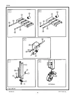
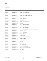
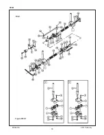
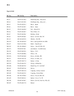
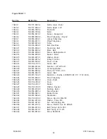
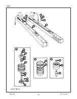
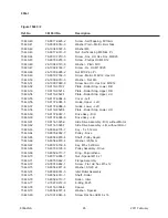
Page 80: ...Figure 6166 800at 2011 February 800at NA ...

Page 81: ...trap Wire 6166 5 78 8010 7163 6 Screw Hex Hd M5 x 10 6166 6 78 8005 5741 1 Washer Flat M5 6166 7 78 8010 7417 6 Nut Hex M5 6166 8 78 8060 7631 7 Connector 3 8 Inch 6166 9 78 8060 8154 9 Sleeving 0 90 MT 6166 10 78 8060 8029 3 Clamp 140 x 3 5 6166 11 78 8100 1219 1 Cover Housing 6166 12 78 8017 9018 5 Washer Plain M4 6166 13 78 8010 7157 8 Screw Hex Hd M4 x 10 2011 February 800at NA ...

Page 82: ...70 THIS PAGE IS BLANK ...

Page 83: ... s serial number s here Important Safety Information BEFORE INSTALLING OR OPERATING THIS EQUIPMENT Read understand and follow all safety and operating instructions It is recommended you immediately order the spare parts listed in the Spare Parts Service Information section These parts are expected to wear through normal use and should be kept on hand to minimize production delays Spare Parts 3M In...

Page 84: ......

Page 85: ...nical Assistance Replacement Parts and Additional Manuals Call the 3M Matic Help line at 1 800 328 1390 Provide the customer support coordinator with the model machine name machine type and serial number that are located on the identif cation plate For example Model Accuglide 2 STD 2 inch Type 10500 Serial Number 13282 Minimum billing on parts orders will be 25 00 Replacement part prices available...

Page 86: ...THIS PAGE IS BLANK ...

Page 87: ...th each machine is an Instructions and Parts List manual SERVICE REPLACEMENT PARTS AND ADDITIONAL MANUALS AVAILABLE DIRECT FROM Order parts by part number part description and quantity required Also when ordering parts or additional manuals include model machine name machine type and serial number that are located on the identification plate 3M Matic AccuGlide and Scotch are Trade marks of 3M St P...

Page 88: ...THIS PAGE IS BLANK ...

Page 89: ... Operation 9 11 Tape Loading Upper Taping Head 10 Tape Loading Lower Taping Head 10 11 Maintenance 12 13 Blade Replacement 12 Blade Guard 12 Blade Oiler Pad 12 Cleaning 13 Applying Buffing Roller Replacement 13 Adjustments 14 16 Tape Latch Alignment 14 Tape Drum Friction Brake 14 Applying Mechanism Spring 15 One Way Tension Roller 15 Tape Leg Length 16 Leading Tape Leg Length Adjustment 16 Changin...

Page 90: ...years after delivery If any part is defective within this warranty period your exclusive remedy and 3M s and seller s sole obligation shall be at 3M s option to repair or replace the part 3M must receive actual notice of any alleged defect within a reason able time after it is discovered but in no event shall 3M have any obligation under this warranty unless it receives such notice within five 5 b...

Page 91: ...ard 3M Matic case sealers The compact size and simplicity of the taping head also makes it suitable for mounting in box conveying systems other than 3M Matic case sealers This includes replacement of other types of taping gluing or stapling heads in existing case sealing machines The AccuGlide 2 STD Taping Heads have been designed and tested for use with Scotch pressure sensitive film box sealing ...

Page 92: ...2 THIS PAGE IS BLANK ...

Page 93: ...f it is possible please have the manual name part number and revision information and or model machine name machine type and serial number that are located on the identification plate For example Model Accuglide 2 STD 2 inch Type 10500 Serial Number 13282 NOTE All the important warning notes related to the operation of the machine are identified by the symbol Updating the Manual Modifications to t...

Page 94: ...e system is running To reduce the risk associated with sharp blade hazards Keep hands and fingers away from tape cutoff blades under orange blade guards The blades are extremely sharp Explanation of Signal Word Consequences Indicates a potentially hazardous situation which if not avoided may result in minor or moderate injury and or property damage CAUTION Indicates a potentially hazardous situati...

Page 95: ...ing Label not shown Figure 1 1 Replacement Labels 3M Part Numbers 2 STD Taping Head 2010 May Important In the event the following safety labels are damaged or destroyed they must be replaced to ensure operator safety See Replacement Parts Illustrations and Parts Lists for label part numbers ...

Page 96: ...0mm 4 3 4 inches most 3M Matic Case Sealers 90mm 3 1 2 inches with optional 2 inch leg length Width 115mm 4 1 2 inches When upper and lower taping heads are used on 3M Matic case sealers refer to the respective instruction manual specifications for box weight and size capacities 6 Operating Rate Conveyor speeds up to 0 40m s 80FPM maximum 7 Operating Conditions Use in dry relatively clean environm...

Page 97: ...0 May 7 Specif cations continued Figure 2 1 Dimensional Drawing Figure 2 1 Dimensional Drawing 396 mm 15 19 32 in 278 mm 10 15 16 in 13 mm 1 2 in 58 mm 2 9 32 in 405 mm 405 mm 445 mm 17 1 2 in 18 mm 11 16 in 18 mm 11 16 in ...

Page 98: ...50mm 2 inch tape legs if desired but both upper and lower heads must be set to ap ply the same tape leg length See Adjustments Changing Tape Leg Length From 70 to 50mm 2 3 4 to 2 Inches Also the conveyor speed at which the product moves through the taping heads affects the leading and trailing tape leg length See Adjustments sec tion Leading Tape Leg Length Adjustment Tape Width Adjustment Taping ...

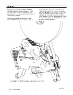
Page 99: ...ping Head Components Threading Diagram Lower Head Left Side View Tape Drum Tape Supply Roll Tape Adhesive Side Tension Wrap Roller Knurled Roller Wrap Roller Threading Needle Applying Roller One Way Tension Roller Applying Mechanism Spring Buff ng Arm Cover Buff ng Roller Orange Knife Guard Tape Cut Off Knife 2 STD Taping Head 2010 May ...

Page 100: ...3 to 3 5 and tape threading la bel Position the tape supply roll so the adhesive side of tape is facing the front of the taping head as it is pulled from the supply roll 3 Attach the threading needle to the end of the roll Guide the threading needle around the wrap roller Position 1 then back around the one way tension roller Position 2 4 Continue pulling the threading needle down and guide it bet...

Page 101: ...oller Figure 3 4 Place tape roll on tape drum to dispense tape with adhesive side forward Seat tape roll fully against back flange of drum Adhere tape lead end to threading needle as shown Figure 3 4 Tape Loading Threading Figure 3 5 Tape Loading Threading WARNING To reduce the risk associated with sharp blade hazards Keep hands and fingers away from tape cutoff blades under orange blade guards Th...

Page 102: ...per and Lower Taping Heads Figure 4 1 1 Loosen but do not remove the blade screws A Remove and discard old blade 2 Mount the new blade B with the beveled side away from the blade holder Maintenance To reduce the risk associated with shear pinch and entanglement hazards Turn air and electrical supplies off on associated equipment before performing any adjustments maintenance or servicing the taping...

Page 103: ...r if the environment in which the heads operate is dusty cleaning on a more frequent basis may be necessary Note Never attempt to remove dirt from taping heads by blowing it out with compressed air This can cause the dirt to be blown inside the components onto sliding surfaces Dirt in these areas can cause serious equipment damage Never wash down or subject taping heads to conditions causing moist...

Page 104: ...r center the tape width on the centerline of the taping head and therefore box center seam Figure 5 2 1 Loosen the locking hex nut behind tape drum bracket on tape drum shaft Use an adjustable wrench or 25mm open end wrench 2 Turn tape drum shaft in or out to center the tape web use 5mm hex wrench 3 Tighten locking hex nut to secure the adjustment No other components require adjustment for tape we...

Page 105: ...rap a cord or small strap non adhesive 4 6 turns around the tension roller 2 Attach a spring scale to the end of the cord or strap 3 Turn the adjusting nut with the socket wrench provided until a force of approximately 0 5 kg to 0 9 kg 1 to 2 lbs is required to turn the roller by pulling on the spring scale One Way Tension Roller Figure 5 5 The one way tension roller is factory set When replacing ...

Page 106: ...oving it closer to the box top or bottom surface will increase the leading leg length Changing Tape Leg Length from 70 to 50mm 2 3 4 TO 2 INCHES Figure 5 7 Note When changing tape leg length both upper and lower heads must be adjusted to apply the same leg lengths Figure 5 6 Leading Tape Leg Length Figure 5 7 Changing Tape Leg Length WARNING To reduce the risk associated with shear pinch and entan...

Page 107: ...ive build up between the knurled roller and its shaft Clean and lubricate shaft Remove all lubricant from roller surfaces Adjust the tape web alignments Position the roller in its mounting slot so that the tape extends just beyond the centerline of the applying roller Check leg length adjustments Replace the blade Increase tape tension by adjusting the one way tension roller Clean and adjust the b...

Page 108: ...ion roller is defective Tape drum not centered Centering guides not centered Box flaps not of equal length Correction Adjust the one way tension roller and or the tape drum assembly Clean adhesive deposits from the surface ends and shafts of the rollers Then lubricate roller shafts Remove all lubricant from roller surfaces Refer to tape cutting problems Re thread the tape Move spring hook to next ...

Page 109: ...er Taping Head Qty Part Number Description 1 78 8017 9173 8 Blade 65 mm 2 56 Inch 2 78 8052 6602 6 Spring Cutter 4 78 8076 4500 3 Stud Mounting 1 78 8070 1273 3 Spring Lower Extension Black 1 78 8076 4726 4 Tool Tape Threading In addition to the above set of spare parts supplied with the taping head it is suggested that the following spare parts be maintained which will require replacement under n...

Page 110: ...part number and part description for the parts in that illustration Note The complete description has been included for standard fasteners and some commercially available components This has been done to allow obtaining these standard parts locally should the customer elect to do so 4 Refer to the first page of this instruction manual Replacement Parts and Service Information for replacement parts...

Page 111: ...1 Taping Head Assemblies AccuGlide 2 STD 2 Inch Figure 10387 Upper Figure 10389 Lower Figure 10391 Figure 10393 Figure 10395 Figure 10397 Upper Figure 10399 Lower Figure 10401 2 STD Taping Head 2010 May ...

Page 112: ...22 2 STD Taping Head 2010 May 22 Figure 10397 Upper Head 11 28 27 27 5 13 13 28 27 7 23 23 21 20 3 1 9 16 8 4 2 5 30 5 26 29 22 13 13 13 5 29 6 15 10 17 17 6 6 13 12 13 24 25 18 6 19 27 28 28 ...

Page 113: ...13 26 1003 5829 5 Screw Hex Hd M6 x 12 10397 15 78 8100 1009 6 Washer Special 10397 16 78 8052 6565 5 Roller Top Tension 10397 17 26 1004 5510 9 Washer Plain M10 10397 18 78 8052 6567 1 Spring Compression 10397 19 78 8017 9077 1 Nut Self Locking M10 x 1 10397 20 78 8052 6569 7 Roller Wrap 10397 21 26 1000 1613 3 Ring Retaining Tru Arc 1 420 0120 100 10397 22 78 8076 4500 3 Stud Mounting 10397 23 7...

Page 114: ...24 2 STD Taping Head 2010 May 2 1 5 4 6 15 14 12 13 12 11 10 4 7 3 15 8 16 9 9 8 16 Figure 10393 Upper and Lower Heads ...

Page 115: ...Assembly 10393 6 78 8070 1266 7 Roller Wrap 10393 7 78 8052 6580 4 Spacer 10393 8 78 8017 9082 1 Bearing Special 30 mm 10393 9 78 8017 9106 8 Screw Bearing Shoulder 10393 10 78 8052 6575 4 Shaft Roller 10393 11 78 8017 9074 8 Washer Nylon 15 mm 10393 12 26 1004 5510 9 Washer Friction 10393 13 78 8052 6567 1 Spring Compression 10393 14 78 8137 1438 9 Assembly Applying Roller 10393 15 26 1003 5829 5...

Page 116: ...26 2 STD Taping Head 2010 May 26 Figure 10387 Upper Head 9 9 1 9 4 5 3 8 7 9 9 2 9 10 11 ...

Page 117: ...fing Arm Sub Assembly 10387 3 78 8052 6575 4 Shaft Roller 10387 5 78 8137 1398 5 Roller Buffing Assembly 10387 7 78 8070 1220 4 Spacer Spring 10387 8 78 8017 9109 2 Shaft 10 x 90 mm 10387 9 26 1003 5829 5 Screw Hex Hd M6 x 12 10387 10 78 8070 1274 1 Spring Upper Silver 10387 11 78 8070 1244 4 Holder Spring 2 STD Taping Head 2010 May ...

Page 118: ...28 2 STD Taping Head 2010 May 28 Figure 10395 Upper and Lower Heads 4 2 1 6 3 3 5 6 4 5 ...

Page 119: ... 10395 2 78 8070 1389 7 Link Arm Bushing Assembly 10395 3 78 8070 1271 7 Shaft Pivot 10395 4 78 8017 9082 1 Bearing Special 30 mm 10395 5 78 8017 9106 8 Screw Bearing Shoulder 10395 6 26 1003 5829 5 Screw Hex Hd M6 x 12 Figure 10395 2 Upper and Lower Heads 2 STD Taping Head 2010 May ...

Page 120: ...30 2 STD Taping Head 2010 May 30 Figure 10391 Upper and Lower Heads 1 2 5 9 8 9 7 3 13 20 4 12 10 14 11 10 15 19 16 7 17 18 13 14 11 12 ...

Page 121: ... Screw Flat Hd Soc Dr M4 x 10 10391 8 78 8017 9135 7 Shaft Spacer 10391 9 78 8052 6600 0 Spacer 10391 10 78 8070 1269 1 Bumper 10391 11 26 1005 4757 4 Screw Flat Hd Soc Dr M5 x 20 10391 12 78 8052 6602 6 Spring Cutter 10391 13 78 8017 9132 4 Pivot Cutter Lever 10391 14 26 1003 5828 7 Screw Spec Hex Hd M6 x 10 10391 15 78 8070 1216 2 Slide Extension 10391 16 26 1008 6574 5 Screw Flat Hd Phil Dr M4 ...

Page 122: ...32 2 STD Taping Head 2010 May Figure 10401 Upper and Lower Heads 4 14 11 15 10 9 8 4 2 7 16 5 6 7 7 14 3 1 13 13 12 13 13 ...

Page 123: ... 10401 6 78 8098 8817 1 Leaf Spring 10401 7 26 1002 5753 9 Screw Self Tapping 10401 8 78 8060 8172 1 Washer Friction 10401 9 78 8052 6271 0 Washer Tape Drum 10401 10 78 8100 1048 4 Spring Core Holder 10401 11 78 8017 9077 1 Nut Self Locking M10 x 1 10401 12 78 8100 1046 8 Spacer Bracket 10401 13 26 1003 5829 5 Screw Hex Hd M6 x 12 10401 14 78 8098 8814 8 Tape Drum Assembly 2 Inch Head 10401 15 26 ...

Page 124: ...34 2 STD Taping Head 2010 May 34 Figure 10399 Lower Head 19 17 18 17 16 25 24 4 1 11 12 6 30 28 27 26 2 5 13 13 23 20 21 7 10 15 23 29 8 6 13 5 13 13 22 5 13 13 28 27 27 28 28 27 3 29 9 22 13 13 6 ...

Page 125: ...6 1003 5829 5 Screw Hex Hd M6 x 12 10399 15 78 8100 1009 6 Washer Special 10399 16 78 8052 6606 7 Roller Tension Bottom 10399 17 26 1004 5510 9 Washer Plain M10 10399 18 78 8052 6567 1 Spring Compression 10399 19 78 8017 9077 1 Nut Self Locking M10 x 1 10399 20 78 8052 6569 7 Roller Wrap 10399 21 26 1000 1613 3 Ring Retaining Tru Arc 1 420 0120 100 10399 22 78 8076 4500 3 Stud Mounting 10399 23 78...

Page 126: ...2 STD Taping Head 2010 May 36 Figure 10389 Lower Head 9 11 7 2 3 8 5 4 1 9 9 10 9 9 9 ...

Page 127: ...fing Arm Sub Assembly 2 10389 3 78 8052 6575 4 Shaft Roller 10389 5 78 8137 1398 5 Roller Buffing Assembly 10389 7 78 8070 1220 4 Spacer Spring 10389 8 78 8017 9109 2 Shaft 10 x 90 mm 10389 9 26 1003 5829 5 Screw Hex Hd M6 x 12 10389 10 78 8070 1273 3 Spring Lower Black 10389 11 78 8070 1244 4 Holder Spring 2 STD Taping Head 2010 May ...

Page 128: ...38 THIS PAGE IS BLANK ...

Page 129: ...39 ...

Page 130: ...40 ...

Reviews: