19
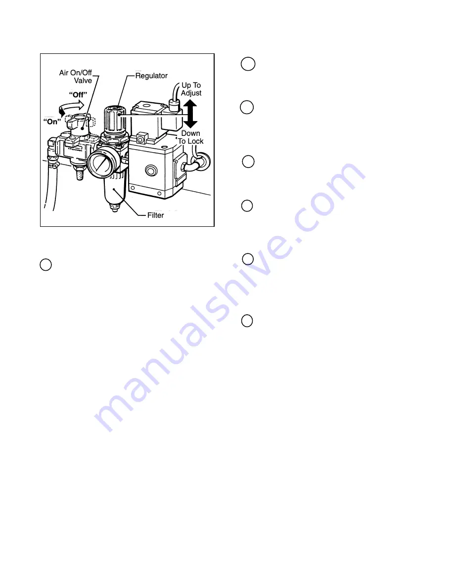
Figure 3-3 "On/Off" Valve/Regulator/Filter
3 Emergency Stop Switch
The 120af is provided with two emergency stop
switches, one on each side of the machine.
The machine electrical supply can be turned off
by pressing the latching emergency stop switch.
To restart machine, rotate emergency stop
switch (releases switch latch) and then restart
machine by pressing green "On" button on
infeed guard.
Operation
(Continued)
4 Indicator, Air Pressure
An optical warning indicator for the compressed
air circuit of the machine indicates "red" when
air circuit is on.
5 Flap Folder Cam
The flap folder cam, when depressed by a box
passing over it, actuates the flap folder to fold
the trailing box flap down. The cam is adjusted
by the operator for the size of box being sealed.
6Height Adjustment Crank
The height adjustment crank moves the upper
assembly (upper taping head) up or down to
adjust for the height of the box being sealed.
7
Drive Belt Adjustment Crank
The drive belt adjustment crank moves the
side drive belts in or out to adjust for the width
of the box being sealed.
8
Side Flap Folder, Upper
The side flap folder guides fold the upper side
flaps of the box down to a closed position prior
to box sealing. The guides are adjusted in or
out to accommodate the width of the box being
sealed.
9
Compression Rollers
The compression rollers push the box side
flaps together for tape sealing. The rollers are
adjusted in or out to accommodate the width of
the box being sealed.
Summary of Contents for 3M Matic 120af
Page 11: ...6 THIS PAGE IS BLANK ...
Page 21: ...16 THIS PAGE IS BLANK ...
Page 31: ...26 THIS PAGE IS BLANK ...
Page 37: ...32 THIS PAGE IS BLANK ...
Page 40: ...35 Special Set Up Procedure Continued Figure 6 3 Outer Column Re Positioning ...
Page 42: ...37 Figure 7 1 Pneumatic Diagram Electrical Pneumatic Diagrams ...
Page 43: ...38 Figure 7 2 Electrical Diagram Electrical Pneumatic Diagrams Continued ...
Page 44: ...39 31 32 23 24 ...
Page 45: ...40 THIS PAGE IS BLANK ...
Page 49: ...44 THIS PAGE IS BLANK ...
Page 50: ...45 120af Adjustable Case Sealer Frame Assemblies ...
Page 51: ...46 Figure 6227 1 of 3 120af Adjustable Case Sealer ...
Page 53: ...48 Figure 6227 2 of 3 120af Adjustable Case Sealer ...
Page 55: ...50 Figure 6227 3 of 3 120af Adjustable Case Sealer ...
Page 57: ...52 Figure 6228 120af Adjustable Case Sealer ...
Page 59: ...54 Figure 6229 120af Adjustable Case Sealer ...
Page 61: ...56 Figure 6230 120af Adjustable Case Sealer ...
Page 63: ...58 Figure 6231 120af Adjustable Case Sealer ...
Page 65: ...60 Figure 6232 120af Adjustable Case Sealer ...
Page 67: ...62 120af Adjustable Case Sealer Figure 6233 1 of 2 ...
Page 69: ...64 Figure 6233 2 of 2 120af Adjustable Case Sealer ...
Page 71: ...66 Figure 6234 120af Adjustable Case Sealer ...
Page 73: ...68 Figure 6235 120af Adjustable Case Sealer ...
Page 75: ...70 120af Adjustable Case Sealer Figure 6236 1 of 2 ...
Page 77: ...72 120af Adjustable Case Sealer Figure 6236 2 of 2 ...
Page 79: ...74 120af Adjustable Case Sealer Figure 6237 ...
Page 81: ...76 Safety and Information Labels 120af Adjustable Case Sealer ...


