32
8.1 Description of the Working Cycle
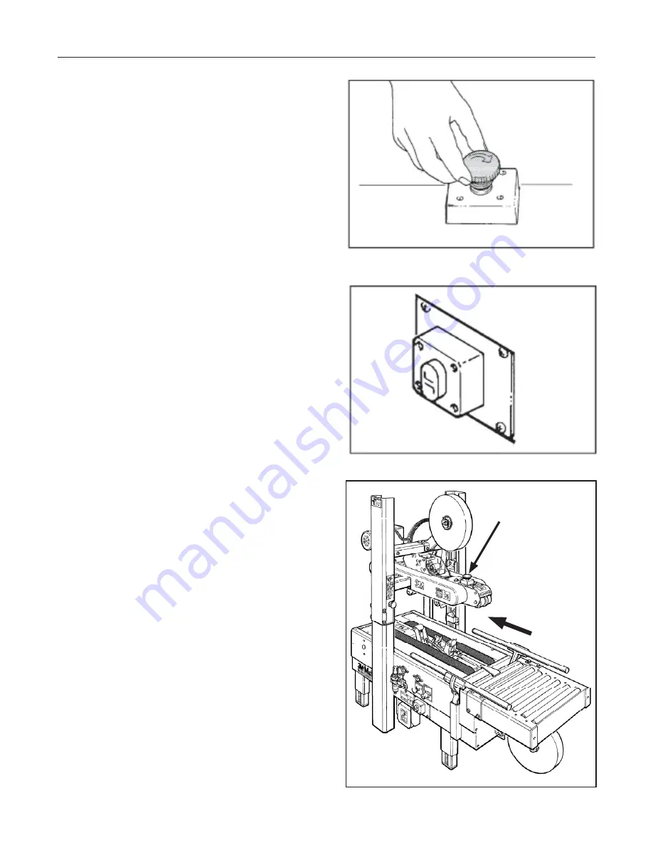
After having closed the top
fl
aps of the carton,
the operator pushes it under the top infeed end
in order to avoid the opening of the top
fl
aps.
Further pushing causes the two top and bottom
belts to drive the box through the taping heads
which automatically seal the top and bottom seams.
The carton is then expelled on the exit conveyor.
8.2 Def
i
nition of Running Mode
The case sealer
700r3
has only one (automatic)
operating mode with:
- The EMERGENCY STOP BUTTON unlocked
(Figure 8-1)
- The main start switch “ON” (I)
(Figure 8-2)
8.3.1 Normal Stop Procedure
When the main switch is turned OFF (O), the
machine stops immediately at any point of the
working cycle. The same thing happens in case
of electrical failure or when the machine is
disconnected from the mains.
8.3.2 Emergency Stop
The LATCHING EMERGENCY STOP BUTTON
is located on the top center of the machine
(Figure 8-1).
8-THEORY OF OPERATION
Figure 8-3
2012 January
700r3-NA
E-Stop Location
Belt
Direction
Figure 8-1
Figure 8-2
Summary of Contents for 3M-Matic 700r3
Page 2: ......
Page 6: ...6 THIS PAGE IS BLANK ...
Page 8: ...iv THIS PAGE IS BLANK ...
Page 60: ...50 THIS PAGE IS BLANK 700r3 NA 2012 January ...
Page 62: ...52 THIS PAGE IS BLANK 700r3 NA 2012 January ...
Page 64: ...54 16 TECHNICAL DIAGRAMS 16 1 Electric Diagram 700r3 NA 2012 January ...
Page 66: ...56 THIS PAGE IS BLANK ...
Page 68: ...58 THIS PAGE IS BLANK ...
Page 70: ...60 THIS PAGE IS BLANK ...
Page 96: ...86 THIS PAGE IS BLANK ...
Page 98: ......
Page 100: ...THIS PAGE IS BLANK ...
Page 102: ...THIS PAGE IS BLANK ...
Page 106: ...2 THIS PAGE IS BLANK ...
Page 126: ...22 AccuGlide 3 3 NA 2012 January Figure 10932 Upper Head AccuGlide 3 3 ...
Page 142: ...THIS PAGE IS BLANK ...
Page 143: ......
Page 144: ......


