45
Adjustments
(continued)
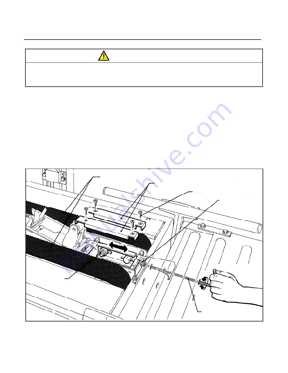
Refer to
Figure 13-8 and 13-9
and adjust belt tension as follows:
1. Remove and retain center plates/front cover and four (4) screws.
2. Loosen, but do not remove, M10 lock nut with a 17mm open end wrench.
3. Reset the tension on the drive belts as needed. Adjust the M8 tension screws in (clockwise) to
increase
tension or out (counterclockwise) to
decrease
tension. Tighten lock nut to secure tension setting.
4. Replace center plates/front cover and secure with original screws.
Figure 13-8 – Box Drive Belt Tension Adjustment, Lower Belts
(Infeed End)
700r3-NA
2012 January
Belt Tension
Screw, M8
Hex Head
Infeed End
Center Plates
Box Drive Belts
M10 Lock Nut
M5 x 10 Flat Hd Screw (4)
M6 Hex Wrench - Special
•
To reduce the risk associated with mechanical and electrical hazards:
−
Turn electrical and air supply off and disconnect before performing any adjustments,
maintenance or servicing the machine or taping heads
WARNING
Summary of Contents for 3M-Matic 700r3
Page 2: ......
Page 6: ...6 THIS PAGE IS BLANK ...
Page 8: ...iv THIS PAGE IS BLANK ...
Page 60: ...50 THIS PAGE IS BLANK 700r3 NA 2012 January ...
Page 62: ...52 THIS PAGE IS BLANK 700r3 NA 2012 January ...
Page 64: ...54 16 TECHNICAL DIAGRAMS 16 1 Electric Diagram 700r3 NA 2012 January ...
Page 66: ...56 THIS PAGE IS BLANK ...
Page 68: ...58 THIS PAGE IS BLANK ...
Page 70: ...60 THIS PAGE IS BLANK ...
Page 96: ...86 THIS PAGE IS BLANK ...
Page 98: ......
Page 100: ...THIS PAGE IS BLANK ...
Page 102: ...THIS PAGE IS BLANK ...
Page 106: ...2 THIS PAGE IS BLANK ...
Page 126: ...22 AccuGlide 3 3 NA 2012 January Figure 10932 Upper Head AccuGlide 3 3 ...
Page 142: ...THIS PAGE IS BLANK ...
Page 143: ......
Page 144: ......


