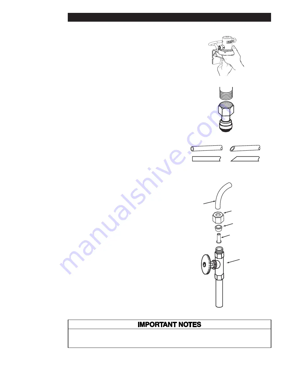
1. Open faucet and turn off cold water supply to relieve pressure.
2. Select and mark a location under the sink that allows ac-
cess for filter change. You will be connecting to the existing
line with 3/8” tubing and various fittings not supplied with
this filter assembly.
3. Using filter head assembly as a guide, fasten filter head as-
sembly to wall with fasteners. (See Figure 1)
Allow 3” clearance from bottom of replacement fi lter for
ease of removal.
4. Place a basin or a towel under the cold water supply valve.
Remove the cold side riser tubing between your cold water sup-
ply valve to your primary faucet connection.
5. Install faucet adapter fitting (Not included, see recom-
mended kit included with 3MDWIKT installation kit) to faucet
stem. This should be a snug fit. Do not overtighten. (See
Figure 2) Ensure the black gasket is inserted into the faucet
adapter prior to assembly.
Determine length of 3/8” tubing (Not included, see recom-
mended kit included with 3MDWIKT installation kit) required
from filter head outlet to faucet adapter by holding tubing in
place ensuring it is of appropriate length. Do not kink tubing as
this will impede water flow. If necessary, loop tubing around to
avoid it being kinked. Cut tubing straight with a razor knife or
tube cutter. (See Figure 3)
6. Insert 3/8” tubing from faucet adapter fitting into the filter
OUTLET fitting as shown in Figure 5.
7. Determine length of 3/8” tubing (Not included, see recommend-
ed kit included with 3MDWIKT installation kit) required from
filter head inlet to cold water supply valve by holding tubing in
place ensuring it is of appropriate length. Do not kink tubing as
this will impede water flow. If necessary, loop tubing around to
avoid it being kinked. Cut tubing straight with a razor knife or
tube cutter. (See Figure 3)
8. Using a ferrule, nut and tube support (Not included, see
recommended kit included with 3MDWIKT installation kit),
slide nut and ferrule over 3/8” tubing, insert tube support
and connect to the cold water supply valve. (See Figure 4)
Insert other end into filter INLET fitting as shown in
Figure 5.
9. Remove sanitary protective cap from filter. Ensure both
o-rings are present on the filter and are seated into grooves;
Correct Incorrect
Figure 3
Figure 4
Figure 2
•
Allow a minimum of 3” (7.6 cm) clear space under the system to facilitate fi lter changes.
•
All components should be accessible and have a suffi cient amount of clearance on all sides of
the system to facilitate servicing.
Figure 1
IMPORTANT INSTALLATION INSTRUCTIONS
Note: White tube from head is a filter vent tube outlet. DO NOT remove, kink or obstruct white tube.
3/8” Tubing
3/8” Compression Nut
3/8” Tube Ferrule
3/8” Tube Support
Cold Water
Supply Valve
The following installation instructions described are based on copper plumbing with 3/8” compression
fittings. Additional fittings may be required to connect to cold water supply.
5
INSTR8029 0512.indd 3
6/13/2012 9:18:09 AM
Summary of Contents for 3MDW201
Page 2: ......


