background image


9

HME

SYS2500D/DS/DSL

Base Station

3M A121 Noise Reduction Module

GND

EXT PLAY CANCEL

20

19

MENU MIC

BASE SPKR CONN

GND (SHIELD)

BASE MIC CONN

VEH DET IN

VEH DET OUT

15

14

13

12

11

16

17

10

9

8

7

6

MENU MIC

GND (SHIELD)

MENU SPKR

MENU SPKR

BASE MIC CONN

WHITE

GREEN

HME MR100A

Message Repeater

MENU
SPKR

MENU
SPKR

SHLD

MIC OUT

5

4

3

2

1

VEHICLE

DETECTOR

MIC OUT

INTERCOM

VEH DET SIG

RED

14

4

5

6

7

8

9

10

BLACK

WHITE

GREEN

VEH DET GND

10

9

8

7

6

11

12

5

GND

OUTPUT

J1

J7

SHLD

13

BLACK

RED

18

ENABLE/DISABLE

BASE SPKR CONN

RED

SHLD

BLACK

VEH DET SIG

VEH DET GND

MIC OUT

MIC OUT

MENU SPKR

MENU SPKR

MENU
SPKR

MENU
SPKR

SHLD

MIC IN

1

2

3

4

5

MIC IN

MENU

SPKR/MIC

OUTSIDE
SPEAKER

Menu Post

MENU

MIC

MENU

SPKR


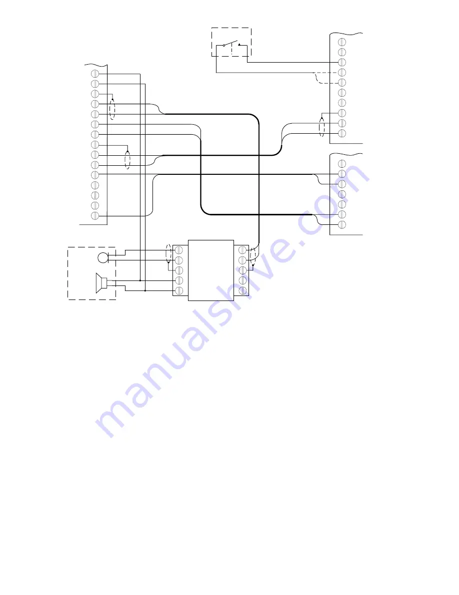
Figure 9.  Wiring for HME SYS2500D/DS/DSL Base Station with HME MR100A Message Repeater 


3M 

Commercial 

Care 

Division 


Food Services trade Department


3M 

Center     

©


3M 

2006 

May 


St. Paul, MN 55144-1000


         78-6912-0699-5 

Rev. 

E


Summary of Contents for 45116

Page 1: ... system with a separate outside microphone and speaker The A121 will not function with an intercom system configured to use a single speaker as both the microphone and speaker The A121 will work in conjunction with most dynamic microphones and speaker microphone assemblies System Configuration The 3M Noise Reduction Module configuration is controlled by two jumper switch JMP1 and JMP2 settings JMP...

Page 2: ...y 3 dB This should be set to the customer s preference SW2 Number ON Position OFF Position 1 Noise Reduction ON Normal Mode Test Mode Factory use only do not change 2 1 Echo Reduction ON Echo Reduction OFF 3 2 Truck Stop Noise Reduction Level 2 Restaurant Noise Reduction Level 4 2 Hi Frequency Equalization ON 2 Hi Frequency Equalization OFF 5 Not Used Not Used Notes Indicates factory settings 1 Mu...

Page 3: ...g is incorrect Wiring is incorrect Check mode configuration Check wiring 3 No outbound audio Wiring is incorrect Check wiring 4 Loud audio in 3M headset when headset user talks Inbound audio on 3M base station too low Increase MENU MIC SENS potentiometer Headset user should then reduce the headset audio volume 5 Excessive echo Excessive feedback from menu speaker to menu mic Add extra acoustic ins...

Page 4: ...4 Figure 2 Wiring for 3M C760 960 1060 Base Station with Interconnect Module ...

Page 5: ...COM MIC IN VEH DET MIC IN SHLD SHLD MIC OUT COM MENU SPKR MIC OUT AUDIO IN A121 Noise Reduction Module 3M Audio Level Control Figure 3 Wiring for 3M C760 960 1060 Base Station with 3M Audio Level Control Module 3M D15 D30 Intercom Menu Post A121 Noise Reduction Module MENU MIC MENU SPKR MENU SPKR MENU SPKR MENU SPKR MENU SPKR SHLD SHLD MIC IN MIC OUT 1 2 3 4 5 5 4 3 2 1 MIC OUT MIC IN MENU INTERCO...

Page 6: ...T ALERT MENU SPKR MENU SPKR SHIELD MIC MIC AUDIO IN VEH DET ALERT OUT COM COM VEH DET AUDIO IN MENU SPKR MENU SPKR MIC MIC J9 J10 A300 Audio Greeter Optional Service Timer 12V UNREG Menu Post MENU SPKR MENU MIC MENU SPKR MENU SPKR MENU SPKR MENU SPKR SHLD SHLD MIC IN MIC OUT 5 4 3 2 1 VEHICLE DETECTOR MIC OUT MIC IN MENU INTERCOM A121 Noise Reduction Module MIC OUT MENU SPKR MIC OUT MENU SPKR 1 2 ...

Page 7: ...TERCOM Menu Post MENU MIC MENU SPKR Figure 6 Wiring for Panasonic WX C510 WX C1010 Base Station HME SYS2500 DS DSL Base Station Menu Post A121 Noise Reduction Module MENU MIC MENU SPKR MENU SPKR MENU SPKR MENU SPKR MENU SPKR SHLD SHLD MIC IN MIC OUT 1 2 3 4 5 5 4 3 2 1 MIC OUT MIC IN MENU INTERCOM OUTSIDE SPKR MIC SPKR MIC SPKR SHIELD OUTSIDE SPKR Needed for HME Hands Free system Figure 7 Wiring f...

Page 8: ...SIC VEH DET GND VEH DET SIG WHITE GREEN SHLD BLACK RED J9 J10 3M A300 Audio Greeter MENU MIC MENU SPKR MENU SPKR MENU SPKR MENU SPKR MENU SPKR SHLD SHLD MIC IN MIC OUT 1 2 3 4 5 5 4 3 2 1 VEHICLE DETECTOR MIC OUT MIC IN MENU INTERCOM VEH DET SIG RED 14 4 5 6 7 8 9 10 BLACK WHITE GREEN VEH DET GND 10 9 8 7 6 11 12 5 GND OUTPUT J1 J7 SHLD 13 BLACK RED Note Set A300 vehicle detector trigger polarity ...

Page 9: ...OUT INTERCOM VEH DET SIG RED 14 4 5 6 7 8 9 10 BLACK WHITE GREEN VEH DET GND 10 9 8 7 6 11 12 5 GND OUTPUT J1 J7 SHLD 13 BLACK RED 18 ENABLE DISABLE BASE SPKR CONN RED SHLD BLACK VEH DET SIG VEH DET GND MIC OUT MIC OUT MENU SPKR MENU SPKR MENU SPKR MENU SPKR SHLD MIC IN 1 2 3 4 5 MIC IN MENU SPKR MIC OUTSIDE SPEAKER Menu Post MENU MIC MENU SPKR Figure 9 Wiring for HME SYS2500D DS DSL Base Station ...

Reviews: