4
PLUMBING CONNECTIONS
Note: The SGLP100-CL, SGLP200-CL, SGLP100-CL-BP and SGLP200-CL-BP Reverse
Osmosis Water Filtration System requires a minimum 60 psi inlet water pressure. If inlet
water pressure is less than 60 psi, a water booster pump may be required depending on the
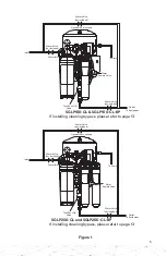
minimum delivery pressure requirements of the downstream equipment. Refer to Figure 1
for proper tubing connections.
All connections are made with “Push-In” connectors. Refer to Figure 2 on the use of
“Push-In” plastic fittings. Use care in routing the tubing to ensure that there are no bends
or kinks.
1. Shut off water supply and water booster pump (if applicable). Water supply line to RO
must be 3/8” tubing.
2. Insert one end of the 1/2” tubing in the inlet port of the RO system.
3. Run 3/8” tubing (not included) from the RO outlet to the inlet of the Foodservice
Equipment. See Figure 1.
4. Run a 3/8” tubing (not included) from the “Brine Out” port of the permeate pump to
the drain.
5a. For SGLP100-CL and SGLP100-CL-BP, ensure that the blue flow control is securely
pushed into 1/4” tubing (one end of which is connected to the “brine in” port of the
permeate pump). Insert the other end of that 1/4” tubing with the flow control at the
bottom of the RO Membrane cartridge.
5b. For SGLP200-CL and SGLP200-CL-BP, ensure that the blue flowcontrol is securely
pushed into 1/4” tubing (one end of which is connected to the “brine in” port of the
permeate pump). Insert the other end of that 1/4” tubing with the flow control at the
bottom of the RIGHT-side RO Membrane cartridge. Also, insert the 1/4” tubing from
right-side RO-head at the bottom port of the LEFT-side RO Membrane cartridge.
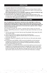
MOUNTING
1. See page 11, Figure 5 for mounting dimensions.
2. Install mounting screws (not included) into the wall or mounting surface as noted in
Figure 5. Be sure to leave a 1/8” to 1/4” space between the bottom of the screw head
and the wall so that the bracket can be hung.
NOTE: Mounting hardware must be capable of supporting a minimum of 50 lbs (22.7 kg).
3. Hang the Bracket/Tank Assembly from the mounting screws.
4. Once the bracket is hung, tighten the mounting screws so that the bracket is snug
between the screw and the wall.
Note: Make sure that the bracket is securely mounted
to a wall stud or other appropriate wall structure.
Summary of Contents for 5636201
Page 12: ...11 Figure 5 5 8 4X 10 1 2 2X 3 4 4X 9 2X 3 8 8X 1 4 4X ...
Page 14: ...13 ...
Page 15: ...14 NOTES ...


