background image

CALIBRATION AND VERIFICATION TEST PROCEDURE 
 

FOR 3M 701 MEGOHMMETER 

 
1. INTRODUCTION 
 

This Specification defines the suggested method of calibration and 
performance verification for the 3M 701 Megohmmeter. It also defines the 
test equipment to be used. 

 
2. TEST EQUIPMENT and DOCUMENTATION 
 

A.  A Keithley Model 619 Electrometer or equivalent (input impedance 

 1 

x 10

). 


B.  A decade box with a range of 1OOK

 to 10G

 ±1 % or the following 

individual resistors: 


100K

 ±1% 

1M

 ±1% 

100M

 ±1% 

100M

 ±1%  

1G

  ±1% 

10G

 ±1% 


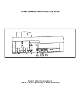
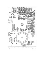
C. Figure 1 - Calibration adjustments  

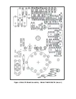
Figure 2 - Main PC Board Assembly issue 1  
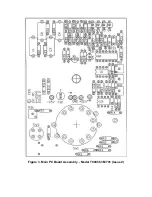
Figure 3 - Main PC Board Assembly - issue 2 
Figure 4 - Main PC Board Assembly - issue 3 

 
3. VERIFICATION PROCEDURE 
 

A.  Place selector switch in the OFF position and adjust the mechanical 

zero to the left end of the scale. 


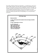
B.  Place selector switch in the BATTERY TEST mode. Verify that pointer 

is in the green (100V) area on the BATTERY TEST scale. 


C.  Place the 100K

 resistor across the input. Switch the unit to 

CONTINUITY TEST. Verify that the unit reads within limits (± 2° of 
100K

 mark on the CONTINUITY TEST scale. Short the input; verify 

that the unit has full-scale deflection. 


D.  Remove the short; place the decade box across the input. Verify that 

the unit reads within limits for 10G

 and 1 M

 in both the 10V and 

100V SURFACE TEST modes. (Tolerances for the 1 M

 / 10 G


Summary of Contents for 701

Page 1: ...issue 1 Figure 3 Main PC Board Assembly issue 2 Figure 4 Main PC Board Assembly issue 3 3 VERIFICATION PROCEDURE A Place selector switch in the OFF position and adjust the mechanical zero to the left end of the scale B Place selector switch in the BATTERY TEST mode Verify that pointer is in the green 100V area on the BATTERY TEST scale C Place the 100KΩ resistor across the input Switch the unit to...

Page 2: ...ll scale Release TEST button E Return the selector switch to BATTERY TEST Press the TEST button Adjust R36 so that the pointer lies over 100V mark on BATTERY TEST scale For Issue 1 PC Boards adjust the value of R8 to align the pointer as above You will be able to find the issue number in the vicinity of the TEST switch on the PC board Release the TEST button F Place the unit in its case Verify tha...

Page 3: ...701 MEGOHMMETER VERIFICATION CALIBRATION Figure 1 Calibration Adjustments R36 is located on opposite edge of printed circuit board ...

Page 4: ...Figure 2 Main PC Board Assembly Model T00456 3M 701 Issue 1 ...

Page 5: ...Figure 3 Main PC Board Assembly Model T00456 3M 701 Issue 2 ...

Page 6: ...Figure 4 Main PC Board Assembly Model T00456 3M 701 Issue 3 ...

Page 7: ...or intervals 100 kilohms 1megohm 10 megohms 100 megohms 1gigaohm and 10 gigaohms marks located on the top scale So to check the 701 for resistance measurement accuracy you need to test resistances at the major intervals and confirm that the readings fall within the dots Please be aware that we are faxing the calibration procedure for the 701 Megohmmeter to you at the fax number listed below ...

Reviews: