

readings are shown on the top scale of the meter as small dots on
either side of the respective resistance mark on the dial.)
E. Remove the decade box. Using the Keithley 619, verify that the output
is between 93V and 107V in the 100V SURFACE TEST mode.
F. If above specifications can not be obtained proceed to Section 4,
Calibration Procedures
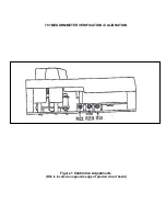
4. CALIBRATION PROCEDURES
A. Place the batteries in the unit. Place the selector switch in the BATTERY
TEST position.
B. Press the TEST button, adjust R10 so that 10.00 V ± .01V appears
between U2 Pin 7 and ground. Release the TEST button.
C. Press the TEST button. Adjust R23 for 100.0V ± .1V between SW 1 Pin 12
and ground. Release the TEST button.
D. Place the selector switch in 100V SURFACE TEST position. Short the
input jacks. Press TEST button. Adjust R21 so that pointer reads full
scale. Release TEST button.
E. Return the selector switch to BATTERY TEST. Press the TEST button.
Adjust R36 so that the pointer lies over 100V mark on BATTERY TEST
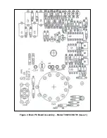
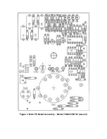
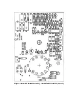
scale. (For Issue 1 PC Boards, adjust the value of R8 to align the pointer,
as above. You will be able to find the issue number in the vicinity of the
TEST switch on the PC board.) Release the TEST button.
F. Place the unit in its case. Verify that the unit reads within the tolerance
limits for the following resistances in both the 10V and 100V SURFACE
TEST modes: 100K
Ω
, 1 M
Ω
, 10M
Ω
, 100M
Ω
, 1G
Ω
, 10G
Ω
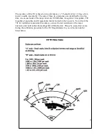
. (Tolerances for
the 1 M
Ω
- 10G
Ω
readings are shown on the top scale of the meter as
small dots on either side of the resistance range. For the 100K
Ω
range,
estimate
±
2° either side of the 100K
Ω
mark on the upper scale of the
meter.)
G. Verify that the unit reads properly with a short and then a 100K
Ω
resistance across the test leads in the CONTINUITY TEST mode. (NOTE:
for the 100K
Ω
range, estimate
±
2° either side of the 100K
Ω
mark on the
continuity scale of the meter.)


