


7
1.0 APPLICATIONS
1.1 PURPOSE:
Hauling Kits are to be used as components in Personal Fall Protection Systems, designed to provide
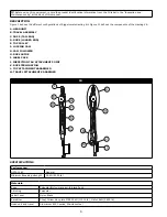
mechanical advantage for raising or lowering a load. More information on hauling kits and engineered systems can be
found in NFPA 1500 and NFPA 1983. Also refer to ANSI Z359.1, Z359.4 and local governing regulations for safe rescue
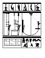
operations. Hauling Kits are typically used as part of a Rescue or Controlled Descent system (see Figure 2):
A
Fall Arrest (AS/NZS1891.4):
Personal fall arrest systems typically include a Full Body Harness and a connecting subsystem
(Energy Absorbing Lanyard, Self-Retracting Device, etc.). Maximum arresting force must not exceed 6 kN (1,349 lb). Maximum
free fall distance 2m (6.6 ft). Anchorage Strength: Selected anchorage must sustain loads of 15 kN (3,372 lb) for single person use
or 21kN (4721 lb) or greater for 2 person use.
B
Work Positioning (AS/NZS1891.4):
Work positioning systems typically include a Full Body Harness, positioning lanyard, and a
back-up personal fall arrest system. For work positioning applications, connect the work positioning subsystem (example: lanyard,
Y-lanyard, etc.) to the lower (hip level) side or belt mounted work positioning attachment anchorage elements (D-Rings). Never
use these connection points for fall arrest. Maximum free fall distance 0.6m (2 ft)Anchorage Strength: Selected anchorage must
sustain loads of 12 kN (2698 lb) for single person use or 18kN (4047 lb) or greater for 2 person use.
C
Climbing (AS/NZS1891.3):
The Full Body Harness is used as a component of a climbing system to prevent the user from falling
when climbing a ladder or other climbing structure. Climbing systems typically include a Full Body Harness, vertical cable or rail
attached to the structure, and climbing sleeve. For ladder climbing applications, harnesses equipped with a frontal D-Ring in the
sternal location may be used for fall arrest on
fi
xed ladder climbing systems. Sternal.
Anchorage Strength:
Structure to which the
climbing system is attached must sustain the loads required by the climbing system manufacturer’s documentation.
D
Rescue:
Rescue systems are con
fi
gured depending on the type of rescue. For limited access (con
fi
ned space) applications,
harnesses equipped with D-Rings on the shoulders may be used for entry and egress into con
fi
ned spaces where worker pro
fi
le is
an issue.
E
Controlled Descent:
For controlled descent applications, harnesses equipped with a single sternal level D-Ring, one or two
frontal mounted D-Rings, or a pair of connectors originating below the waist (such as a seat sling) may be used for connection to a
descent or evacuation system.
F
Restraint (AS/NZS1891.4)
: The Full Body Harness is used as a component of a restraint system to prevent the user from
reaching a fall hazard. Restraint systems typically include a Full Body Harness and a lanyard or restraint line.
1.2 STANDARDS:
The Hauling Kits included in this manual conform to the standard(s) identi
fi
ed on the front cover of
this instruction. If this product is resold outside the original country of destination, the re-seller must provide these
instructions in the language of the country in which the product will be used.
1.3 TRAINING:
It is the responsibility of the user and the purchaser of this equipment to assure that they are familiar with
these instructions, trained in the correct care and use of, and are aware of the operating characteristics, application limits,
and the consequences of improper use of this equipment.
1.4 LIMITATIONS:
Always consider the following application limitations before using this equipment:
• CAPACITY:
The Hauling Kit is rated to 59-282kg (130-620lb), minimum breaking strength of 36 kN (8093 lb). Make
sure all of the components in your system are rated to a capacity appropriate to your application.
• FREE
FALL:
Personal fall arrest systems used with this equipment must be rigged to limit the free fall to 2 m (6.6 ft)
1
.
Restraint systems must be rigged so that no vertical free fall is possible. Work positioning systems must be rigged so
that free fall is limited to 0.6 m (2 ft) or less. Personnel riding systems must be rigged so that no vertical free fall is
possible. Climbing systems must be rigged so that free fall is limited to 0.46 cm (18 in) or less. Rescue systems must
be rigged so that no vertical free fall is possible. See subsystem manufacturer’s instructions for more information.
• FALL
CLEARANCE:
Figure 3 illustrates the components of a Fall Arrest. There must be suf
fi
cient Fall Clearance (FC)
to arrest a fall before the user strikes the ground or other obstruction. Clearance is affected by a number of factors
including: (A) Lanyard Length, (B) Lanyard Deceleration Distance or SRL Maximum Arrest Distance, (C) Harness
Stretch and D-Ring/Connector Length and Settling (typically a Safety Factor of 1 m (3.3 ft). Refer to the instructions
included with your Fall Arrest subsystem for speci
fi
cs regarding Fall Clearance calculation.
• SWING
FALLS:
Swing Falls occur when the anchorage point is not directly above the point where a fall occurs (see Figure
4). The force of striking an object in a swing fall may cause serious injury or death. Minimize swing falls by working as
directly below the anchorage point as possible. Do not permit a swing fall if injury could occur. Swing falls will signi
fi
cantly
increase the clearance required when a Self-Retracting Device or other variable length connecting subsystem is used.
• EXTENDED
SUSPENSION:
A Full Body Harness is not intended for use in extended suspension applications. If the
user is going to be suspended for an extended length of time it is recommended that some form of seat support be
used. 3M recommends a seat board, suspension work seat, seat sling, or a boatswain chair. Contact 3M for more
information on these items.
• ENVIRONMENTAL
HAZARDS:
Use of this equipment in areas with environmental hazards may require additional
precautions to prevent injury to the user or damage to the equipment. Hazards may include, but are not limited to;
heat, chemicals, corrosive environments, high voltage power lines, gases, moving machinery, and sharp edges.
• ENVIRONMENT:
This equipment is design for use between -40° and 60°Celsius (-40 and 140° F).
1 Fall Arrest Free Falls:
Free falls greater than 2 m (6.6 ft) may be permitted when users are secured to the anchorage with a connecting subsystem which limits
maximum arresting force to 6 kN (1,349 lb) and is authorized for such use (i.e., 3M Force 2™ Lanyards).


