


78-8124-4524-1-B
2
5.0 Install Mold Body
5.1
Trim mold ends with knife to fit cable slightly loose. Hold
mold halves in place, centered over splice (bend branch
cable to accommodate centering of mold). Snap mold halves
together firmly. Check to see that both seams are carefully
snapped together. Tape ends of mold body around cable to
seal. Use supplied Scotch
™
Electrical Tape 23 (see Figure 2).
IMPORTANT: Stretch tape to 3/4 original width.
5.2
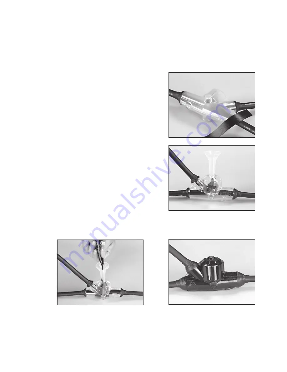
Put pouring spout in hole.
Note: The preferred pouring position is as indicated in
Figure 3. This kit can, however be poured from either
side if necessary. Cut thin membrane from port at top
of desired pouring position. Insert pouring spout and
plug remaining hole with small plastic plug provided
in kit.
Figure 2
Figure 3
Figure 4
Figure 5
6.0 Pour Splice
6.1
Position splice level. Mix resin thoroughly per instructions on resin package. Pour resin until mold and
spout are completely filled (see Figure 4). Refill spout after air escapes. When resin has solidified and
cooled, splice may be put into service. Clip off spout, if desired (see Figure 5).
4.0 Make Connection
4.1
Make connection according to instructions for connector being used. The mold will accept:
a) Crimped type connectors up to 2/0 AWG b) Split bolt connectors up to 1/0 AWG
4.2
For Multi-Conductor cables
, stagger individual connections and insulate with Scotch 23 Electrical
Tape. Sheath opening should not exceed 3". Use 3M
™
Scotchlok
™
Connector or indent-type connectors.
Summary of Contents for 90-B1
Page 7: ......


