background image

23

Bair Hugger Model 750 Temperature Management Unit Service Manual 

English 202522A

Check the 3M

TM 

Bair Hugger

TM

 therapy website to ensure you have the most recent version of this document. 

www.bairhugger.com reorder #202522A

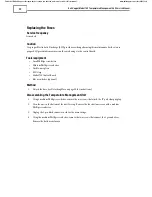
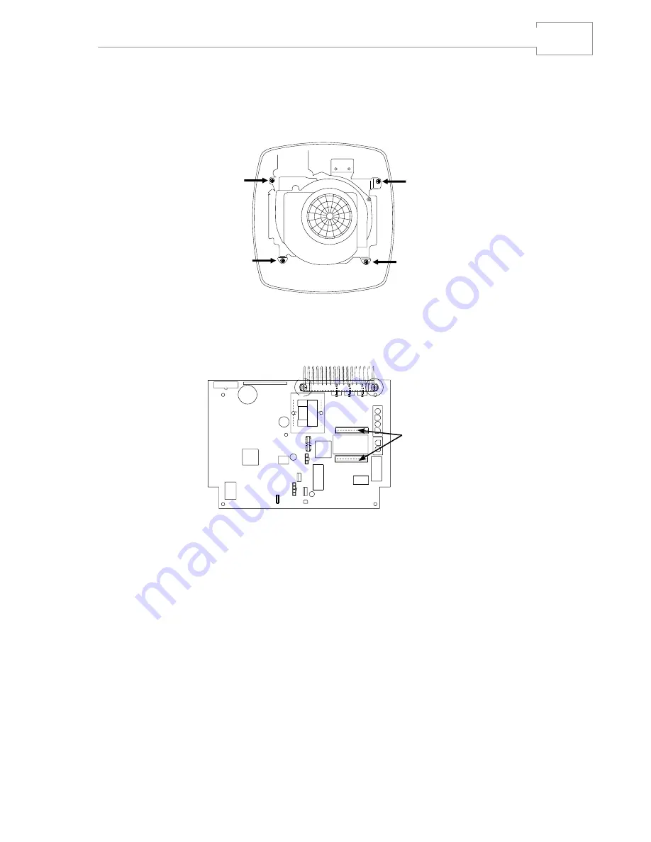
5�  Using the medium Phillips screwdriver, remove the four screws that hold the chassis assembly to the 

top enclosure (Figure 2)�

6�  Unplug the user interface and LCD connector to remove the top enclosure� If needed, use a flat 

screwdriver to lift and release the snap-fit LCD connector�

7�  Replace fuses� 

fuses

Reassembling the Temperature Management Unit

1�  Plug in the user interface and LCD connectors�

2�  Attach the chassis assembly to the top enclosure with the 4 screws�

3�  Screw in the two ground wires (with the 2 screws)�
4�  Plug in the 2-pin black connector�
5�  Attach the bottom to the top enclosure with the 4 screws�
6�  Attach the IV pole clamp or plug (with the 2 pole clamp screws)�

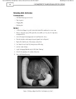
7�  Reattach the hose (see reattaching the hose on page 21 for instructions)�

Summary of Contents for Bair Hugger 750

Page 1: ...n Sie im Betriebshandbuch für das Modell 750 Bitte an die Abteilung für biomedizinische Technik weiterleiten 2 Manuel d entretien du module de réchauffement Bair Hugger modèle 750 Pour de plus amples informations concernant le fonctionnement de l unité de régulation thermique modèle 750 veuillez consulter le manuel de l utilisateur du modèle 750 Merci de transmettre au service d ingénierie biomédi...

Page 2: ...Check the 3MTM Bair HuggerTM therapy website to ensure you have the most recent version of this document www bairhugger com reorder 202522A ...

Page 3: ...er Model 750 Warming Unit Service Manual English 1 Français 33 Deutsch 67 Check the 3MTM Bair HuggerTM therapy website to ensure you have the most recent version of this document www bairhugger com reorder 202522A ...

Page 4: ...Check the 3MTM Bair HuggerTM therapy website to ensure you have the most recent version of this document www bairhugger com reorder 202522A ...

Page 5: ...ating Temperatures 11 Testing the Over Temperature Detection System 13 Viewing the Fault Code Log 15 Clearing the Fault Code Log 15 Fault Code Table 16 Viewing the Hour Meter 17 Viewing the Operating Timer 17 Replacing the Air Filter 18 Replacing the Hose 19 Reattaching Hose 20 Replacing the Fuses 21 General Maintenance and Storage 23 Cleaning the Cabinet and Hose 23 Storage 23 Troubleshooting 24 ...

Page 6: ...he unit is turned ON and a temperature setting is selected warm air flows over the Model 241 tubing and warmed fluid exits from the distal end of the tubing For additional information on Bair Hugger blankets Bair Paws gowns the 241 blood fluid warming set or other accessories visit us online at bairhugger com or bairpaws com This manual includes operating and service instructions and unit specific...

Page 7: ...lation Please consult IEC 60601 1 2005 for requirements Fuse Nonexplosion proof Type BF equipment patient applied VAC V Voltage alternating current AC This system is subject to European WEEE Directive 2002 96 EC This product contains electrical and electronic components and must not be disposed of using standard refuse collection Please consult local directives for disposal of electrical and elect...

Page 8: ...ermal injury may result Always connect the hose to a Bair Hugger blanket or Bair Paws gown before providing therapy 4 Do not place the non perforated side of the blanket on the patient Thermal injury may result Always place the perforated side the side with small holes towards the patient 5 Do not continue temperature management therapy if the Over temp indicator light illuminates and the alarm so...

Page 9: ...et CAUTIONS 1 Except for specific blanket models Bair Hugger blankets are not sterile and are all intended for single patient use ONLY Placing a sheet between the Bair Hugger blanket and the patient does not prevent contamination of this product 2 Monitor the temperature and cutaneous response of patients who are incapable of reacting communicating and or who are without a sense of feeling every 1...

Page 10: ... if the following events occur Modifications or repairs are performed by unqualified personnel The unit is used in a manner other than that described in the Operator s or Service Manuals The unit is installed in an environment that does not meet the appropriate electrical and grounding requirements Read Before Servicing Equipment All repair calibration and servicing of the Bair Hugger model 750 te...

Page 11: ...e 1 Unit Power On Reset The Model 750 temperature management unit performs the following power on reset sequence after you connect the unit to a grounded power source Performs all self test functions Illuminates all indicator lights and all pixels in the alphanumeric display momentarily Displays the text MD 700 s and the software revision level in the alphanumeric display Produces 3 chirping sound...

Page 12: ... a temperature mode the following events occur Corresponding indicator light illuminates Blower operates Heater activates except in Ambient mode Temperature mode timer and hour meter activate Temperature at the blanket end of the hose appears in the alphanumeric display Temp in Range indicator light illuminates when the temperature at the blanket end of the hose is within 1 5 C of the selected set...

Page 13: ...e alphanumeric display Up to 5 fault codes are stored in memory When the audible alarm sounds press any button on the keypad to temporarily silence it The temperature management unit must be unplugged before it can be restarted See Viewing the Fault Code Log and the Fault Code Table for more information about specific fault codes Over Temperature Condition When an overtemperature condition exists ...

Page 14: ...e maintenance and always after servicing the temperature management unit or replacing the hose The hose end sensor temperature can be altered a maximum of 3 0 C by adjusting the calibration offset value In the Calibration mode the temperature management unit operates in the Ambient temperature mode and the alphanumeric display shows the current hose end sensor temperature and calibration offset wi...

Page 15: ...on Alternative Mode button Over temperature Detection Test AltMode4 System Information AltMode3 Fault Code Log AltMode2 Calibration AltMode1 To enter one of the Alternative modes press the Alternative Mode button in combination with one of the operating mode buttons also located on the front panel Figure 2 indicates which keys must be pressed to enter each of the 5 Alternative modes When the corre...

Page 16: ...here Improper measurement or adjustment of the temperature management unit s normal operating temperature could result in patient exposure to temperatures outside of the indicated range and may lead to patient injury Service frequency Every 6 months or 500 hours of use or whenever service is performed Tools equipment Model 22110 Temperature Test Unit NOTES The Model 22110 Temperature Test Unit sim...

Page 17: ...indicator lights flash Blower activates Heater elements deactivate The text TMP and the temperature in C 0 1 C resolution at the end of the hose appear in the alphanumeric display The text OS and the current calibration offset value 0 1 C resolution appear in the alphanumeric display 5 Compare the temperature shown on the alphanumeric display and the temperature on the independent temperature cali...

Page 18: ...Temperature skip to step 4 note If the temperature management unit has been stored at a temperature lower than 20 C allow it to reach ambient temperature before beginning the test 1 Connect the temperature management unit to a grounded power source The unit performs a self test and automatically proceeds to Standby mode 2 Connect the temperature test kit to the hose of the temperature management u...

Page 19: ...e messages 1 OT Test OT Test PASS Prx OR PASS Dst 2 TestTime XX Secs 3 Unplug To Reset b FAIL Unit did not detect an over temperature condition within 150 seconds time out failure An alarm sounds and the Fault indicator light flashes The text FAIL flashes in the alphanumeric display followed by these messages 1 OT Test FAIL 2 TestTime 150 Secs 3 Unplug To Reset NOTE Do not place a temperature mana...

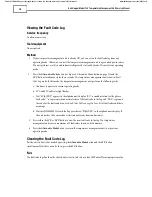
Page 20: ...operate in current operating mode b 32 C and 38 C indicator light flashes c Text FC n XXX appears in the alphanumeric display FC is an abbreviation for the phrase fault code n represents the numerical order of the fault code in the log and XXX represents the code for the fault condition See Fault Code Table on page 16 for a list of fault codes and their meanings d The time HH MM SS of each fault a...

Page 21: ... failure 008 Medium wattage heater failure 009 High wattage heater failure 010 A D converter timeout 011 A D startup check failed 012 Reserved Fault Code 013 Error in execution loop 014 Timeout on alphanumeric display busy flag clearing 015 RAM corruption in duplicate RAM locations 016 Error in executing a depressed key 017 Stuck key during startup 050 EEPROM is at max write cycles 051 Non 0 EEPRO...

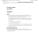
Page 22: ...s the Alternative Mode button for three seconds see Figure 2 The temperature management unit is now in Hour Meter Display mode In this mode the temperature management unit performs the following tasks a Continues to operate in current operating mode b Hours appears in the alphanumeric display c Cumulative hours of temperature management unit operation appear in the alphanumeric display 3 Wait 60 s...

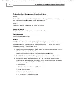
Page 23: ...rdous microorganisms Discard the filter in a manner consistent with institutional protocol for biohazardous material Method 1 Disconnect the temperature management unit from the grounded power source 2 Turn the temperature management unit upside down 3 Remove the 2 screws located in the louvered filter cover 4 Lift the filter cover off the temperature management unit 5 Remove the air filter and di...

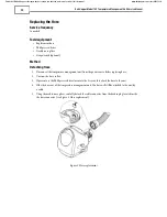
Page 24: ...ench optional Method Detaching Hose 1 Disconnect the temperature management unit from the power source before replacing hose 2 Unscrew the hose collar 3 If present use the Phillips screwdriver to remove the 2 screws that attach the hose to the unit 4 Slide the hose out of the temperature management unit The hose will still be attached to the unit by a cable 5 Using the needle nose pliers carefully...

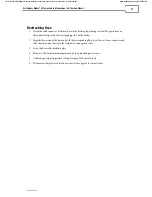
Page 25: ...that the protrusions on the connector align with the corresponding slots on the header 2 Align the flat section of the hose end with the corresponding flat part of the unit s hose connector and slide the replacement hose into the temperature management unit 3 Screw the hose collar back into place 4 Reconnect the temperature management unit to a grounded power source 5 Calibrate operating temperatu...

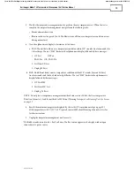
Page 26: ...t Small Phillips screwdriver Medium Phillips screwdriver Needle nose pliers ESD strap Model 750 Control Board Flat screwdriver optional Method 1 Detach the hose see Detaching Hose on page 20 for instructions Disassembling the Temperature Management Unit 1 Using a medium Phillips screwdriver remove the two screws that attach the IV pole clamp or plug 2 Turn the unit so the bottom of the unit faces ...

Page 27: ... connector to remove the top enclosure If needed use a flat screwdriver to lift and release the snap fit LCD connector 7 Replace fuses fuses Reassembling the Temperature Management Unit 1 Plug in the user interface and LCD connectors 2 Attach the chassis assembly to the top enclosure with the 4 screws 3 Screw in the two ground wires with the 2 screws 4 Plug in the 2 pin black connector 5 Attach th...

Page 28: ...t or hose while cleaning Moisture will damage the components and thermal injury may result cautions Do not use a dripping wet cloth to clean the cabinet Moisture may seep into the electrical contacts and damage the components Do not use alcohol or other solvents to clean the cabinet Solvents may damage the labels and other plastic parts Method 1 Disconnect the temperature management unit from the ...

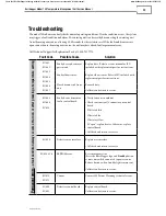
Page 29: ...FC 004 FC 005 FC 006 FC 007 Faulty hose end sensor at patient end Replace hose Refer to service manual or IFU included with replacement part for instructions Faulty elbow sensor Replace elbow sensor Refer to IFU included with replacement part for instructions Hose disconnected from unit Reattach hose Calibrate and return to service FC 008 FC 009 FC 010 Faulty heater element or faulty control board...

Page 30: ... source Remove hose occlusion Position hose end correctly into hose card refer to the operator s manual Wait 30 60 seconds before reconnecting to the main power source Reconnect to power source If no fault occurs unit is ready for use FC 002 FC 003 FC 004 FC 005 FC 006 FC 007 Hose end sensor failure at blanket end Faulty elbow sensor Moisture Intermittent sensor failure High heat Disconnect from p...

Page 31: ...r label is located on the back or side of the unit In Warranty Repair and Exchange usa Call 3M Patient Warming customer service if your Model 750 temperature management unit requires factory service A customer service representative will give you a Return Authorization RA number Please use this RA number on all correspondence concerning your temperature management unit Your customer service repres...

Page 32: ... service carton 2 Remove the top foam piece If the plastic liner is available use it to enclose the temperature management unit 3 Lower the temperature management unit carefully into the carton 4 Place the unit hose on the temperature management unit see Figure 4 5 Replace the top foam piece Observe proper orientation 6 Lay the unit hose on top of the foam piece around the edge 7 Seal the carton w...

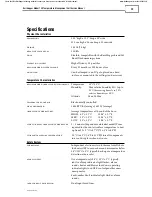
Page 33: ...humidity at 40 C Altitude Max 2 000m temperature control Electronically controlled heat generated 1644 BTU hr average 482 W average operating temperatures Average temperatures at the end of the hose HIGH 43 1 5 C 109 4 2 7 F MED 38 1 5 C 100 4 2 7 F LOW 32 1 5 C 89 6 2 7 F time to reach operating temperature 2 5 minutes dependent on blanket model Time required for the contact surface temperature t...

Page 34: ...00 A 125 Vac certifications IEC 60601 1 EN 60601 1 2 UL 60601 1 CAN CSA C22 2 No 601 1 EN 55011 EN 80601 2 35 classification MEDICAL GENERAL MEDICAL EQUIPMENT AS TO ELECTRICAL SHOCK FIRE AND MECHANICAL HAZARDS ONLY IN ACCORDANCE WITH UL 60601 1 CAN CSA C22 2 No 601 1 ANSI AAMI ES60601 1 2005 CSA C22 2 No 60601 1 08 EN 80601 2 35 Control No 4HZ8 Classified under IEC 60601 1 Guidelines and other nat...

Page 35: ... Ambient button together for approximately 3 seconds b Temperature measured at end of hose will display on LCD 4 Adjust Bair Hugger unit s displayed temperature so it matches test unit sensor 1 increments a 32 C button lowers displayed temperature b 43 C button raises displayed temperature Note Unit can only adjust 3 0 C Try a different hose if more adjustment is required and call 3M Patient Warmi...

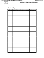
Page 36: ... Management Unit Service Manual 32 Check the 3MTM Bair HuggerTM therapy website to ensure you have the most recent version of this document www bairhugger com reorder 202522A Maintenance Log Date Maintenance Action Performed Hour Meter ...

Page 37: ...RE MANAGEMENT and the BAIR HUGGER logo are trademarks of Arizant Healthcare Inc used under license in Canada 2013 Arizant Healthcare Inc All rights reserved 3M Deutschland GmbH Health Care Business Carl Schurz Str 1 41453 Neuss Germany 3M Health Care 2510 Conway Ave St Paul MN 55144 USA TEL 800 228 3957 www bairhugger com 202522A 07 13 ...

Reviews: