Step 5
Attach Drain Line to Drain Line Fitting. To prevent back pressure from reducing the fl ow rate below minimum required for backwash, Drain Line MUST be sized
according to run length and relative height. Be careful not to bend fl exible drain tubing sharply enough to cause “kinking” (if kinking occurs Drain Line MUST be
replaced). Typical examples of proper Drain Line diameters are:
a.
1/2” ID lengths up to 15 feet and heights lower or slightly higher than the control valve.
b.
5/8” ID length up to 25 feet in length and up to 4 feet above the control valve.
c.
For distances higher or longer than previously stated, relocate the fi lter closer to the desired discharge point or consult
factory for advice. Avoid overhead drain lines as it may prevent desirable performance.
Avoid installing drain overhead or using fl exible vinyl tubing, either may result in failure.
Some areas prohibit the use of fl exible drain lines. Check with local code offi cials prior to installation.
CAUTION
CAUTION
To reduce the risk associated with property damage due to water leakage:
•
Installation must comply
with existing state or local plumbing codes..
Step 6
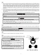
Position Drain Line over drain and secure fi rmly. To prevent back-siphoning of sewer water, provide an air-gap of at least 2 inches or 2 pipe diameters between
end of drain hose and drain (See Figure 3). Do not raise Drain Line more than 10 feet above fl oor.
Step 7
Make certain both inlet and outlet knobs of bypass valve are in "bypass" position. Turn on power to well pump or completely open main supply valve. Check for
leaks and correct as necessary.
Step 8
a)
Manually stage control to Backwash Position (See “How To Manually Backwash Your Filter At Any Time”, Page 2-4). Open Bypass Valve approximately 1/4 of
the way to full open (“Service” Position), allowing unit to fi ll slowly. This will purge entrapped air in the bed.
b)
Once a steady stream of water is fl owing to drain, open Bypass Valve completely. Leave unit in backwash for at least 10 minutes OR until drain line water
runs clear, whichever is longer.
IMPORTANT NOTE
IMPORTANT NOTE
Filters containing activated carbon (A media), or Filter-Ag
®
(F media) must be saturated for at least 2 hours prior to subjecting the unit to full backwash fl ow
rates. Failure to do this may result in loss of mineral during initial backwash procedure.
Step 9
After this preliminary backwash, manually advance Control Valve to “Service” position and plug valve into a 110V, 60Hz properly grounded non-switched power
source.
Step 10
Set time of day (See How To Set Time Control) and set Backwash Frequency (See Determining Backwash Frequency). Installation is now complete.
IMPORTANT NOTE
IMPORTANT NOTE
During the initial backwashings, a small amount of media may be observed in drain water. This is normal and benefi cial for effi cient operation of your fi lter
system.
Step 11
Manually initiate a complete “regeneration” process, allowing the unit to automatically proceed through a backwash and rapid rinse. See “How to Manually Back-
wash Your Filter At Any Time.” Check drain water at end of rapid rinse cycle. If water is cloudy, repeat the backwash process.
IMPORTANT NOTE
IMPORTANT NOTE
Restore fuel supply or power to water heater.
Determining Backwash Frequency
The exact backwash frequency depends on the quality of the raw water, but it is recommended that fi lters containing activated carbon (A media), Filter-Ag
®
(F media),
or Filter Sand (QFS media) be programmed to backwash at least once every six days. If pressure drop becomes excessive or contaminant reappears in the treated
water before six days, increase the frequency.
2-3
Figure 3. DRAIN

