11
78-8124-5866-5-E
3M
™
Cold Shrink QT-lll Silicone Rubber Three Core Inverted Skirted Termination
with High-K Stress Relief
4.0 Install Silicone Rubber Breakout Boot Assembly
4.1
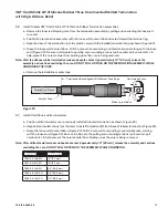
Inspect breakout boot assembly and confirm that all loose plastic core ends are free as shown (Figure 13).
Finger
Neck
Neck Core
Boot Neck
Loose Core Ends
Boot Finger
Finger Core
Loose Core End
Loose Core End
Loose Core End
Figure 13
4.2 To ensure that the breakout boot can be fully seated into the breakout area of the cable, it will be necessary to
unwind a few turns of each finger core.
Caution: Do not unwind too far such that boot fingers begin to collapse.
4.3 Hold loose neck-end core ribbon to one side so that it can not become trapped between cable phases. Slide
boot assembly over cable end; guiding individual cable cores through boot assembly fingers.
Hint: View end of cable through finger cores to ease cable phase insertion.
4.4 Slide breakout boot assembly onto cable as far as it will go. Large neck-end should fully extend over
previously installed jacket sealing assembly tube.
Hint: Spreading cable phases while sliding the boot assembly can ease the installation.
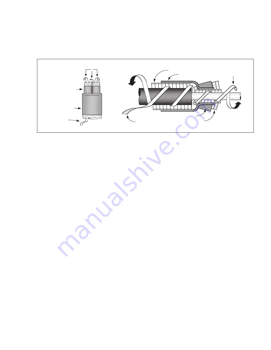
4.5 Remove large neck-end core. Grasping loose core ribbon end, pull and unwind counterclockwise around
cable.
4.6 Remove each finger core. Grasping loose core ribbon end, pull and unwind counterclockwise around each
cable phase leg.


