background image

22

9.0  INSPECTION AND MAINTENANCE LOG

SERIAL NUMBER:

 __________________________________________

MODEL NUMBER:

 ___________________________________________

DATE PURCHASED:

 ______________

DATE FIRST USED:

 __________

INSPECTION 

DATE

INSPECTION 

ITEMS NOTED

CORRECTIVE 

ACTION

MAINTENANCE 

PERFORMED

Approved By:

Approved By:

Approved By:

Approved By:

Approved By:

Approved By:

Approved By:

Approved By:

Approved By:

Approved By:

Approved By:

Approved By:

Approved By:

Approved By:

netzerotools.com

netzerotools.com

Summary of Contents for DBI SALA 8518579

Page 1: ... must be followed for proper use and maintenance of this product Alterations or misuse of this product or failure to follow instructions may result in serious injury or death IMPORTANT If you have questions on the use care application or suitability for use of this safety equipment contact DBI SALA IMPORTANT Before using this equipment record the product identification information from the ID labe...

Page 2: ...s Optional Removable Crank Arm Optional Permanent Crank Arm Carrying Handle Universal Mounting Plate Winch Secondary Drive Hub 9 1 retrieval ratio Primary Drive Hub 4 1 retrieval ratio Power Drive Clutch Optional Power Drive Hub Optional netzerotools com netzerotools com ...

Page 3: ... be independently evaluated and classified for use as a single point suspension system See OSHA regulation 29 CFR 1926 451 and 29 CFR 1910 28 B PERSONNEL RIDING The Digital Winch is used to raise or lower a worker to a work level At the work level the worker is no longer supported by the winch A back up PFAS must be attached to the employee while riding the winch C RESCUE AND EVACUATION The Digita...

Page 4: ...REST SYSTEMS Personal fall arrest systems used with the Digital Winch must meet applicable state and federal regulations and the requirements stated in section 3 3 D PHYSICAL AND ENVIRONMENTAL HAZARDS Use of this equipment in areas with physical or environmental hazards may require that additional precautions be taken to reduce the possibility of damage to this equipment or injury to the user Haza...

Page 5: ...unintentionally disengage see Figure 2 Connectors must be compatible in size shape and strength Self locking snap hooks and carabiners are required by ANSI Z359 1 and OSHA 2 3 MAKING CONNECTIONS Only use self locking snap hooks and carabiners with this equipment Only use connectors that are suitable to each application Ensure all connections are compatible in size shape and strength Do not use equ...

Page 6: ...rebar or cross members that are not shaped in a way that can capture the gate of the hook C In a false engagement where features that protrude from the snap hook or carabiner catch on the anchor and without visual confirmation seems to be fully engaged to the anchor point D To each other E Directly to webbing or rope lanyard or tie back unless the manufacturer s instructions for both the lanyard a...

Page 7: ... factors that affect your safety during use Some important points to consider when planning your system are A HAZARD EVALUATION Evaluate job site hazards prior to starting work Consult applicable OSHA and industry standards for guidelines and regulatory requirements on issues such as confined space entry personal fall arrest systems PFAS and single point adjustable suspended scaffolds B WORK SITE ...

Page 8: ... the anchorage strengths set forth in A and B must be multiplied by the number of PFAS attached to the anchorage Per OSHA 1926 500 and 1910 66 Anchorages used for attachment of a PFAS shall be independent of any anchorage being used to support or suspend platforms and must support at least 5 000 lbs 22 2kN per user attached or be designed and used as part of a complete PFAS which maintains a safet...

Page 9: ...accommodate most other support structures which meet the requirements specified in section 3 3 See the support system user manual for mounting information or contact DBI SALA for optional mounting kits When attaching the winch to the support one of the attachment features i e bolt or stud must capture the structural carrying handle D WELDED INSTALLATIONS If welding the mounting bracket to a suppor...

Page 10: ...plications requiring a secondary PFAS the winch line should be connected to a Y type lanyard and this lanyard Figure 6 Connecting to Winch Line Figure 5 Mounting Bracket DBI SALA Quick Mount Bracket Universal Mounting Plate Clamp Knob Universal Mounting Plate DBI SALA Advanced Series Mounting Bracket Connecting device must capture handle Structural Handle Structural Handle netzerotools com netzero...

Page 11: ...the drum Route the line over the support structure pulley system Refer to the support structure user instructions for cable routing TO RAISE A LOAD Rotate the winch crank handle in the raise direction clockwise To hold or momentarily suspend the load stop cranking The automatic clutch brake will hold the load if handle is released Do not exceed the rated capacity of 450 lbs 204 kg TO LOWER A LOAD ...

Page 12: ...egrity of the attachment and support system as follows A Crank the winch handle in the raise direction until the line is snug The worker should slowly transfer their weight to the harness and lifeline until they are able to lift both feet off the ground B Make sure the winch holds the worker in a stationary position Also adjust the fit of the harness at this time so that it does not pinch chafe or...

Page 13: ...ifeline 3 9 RETRIEVING A WORKER Communicate with the worker when preparing to retrieve them and maintain communication throughout the procedure Place the crank handle in the 4 1 or 9 1 drive hub as appropriate to keep the turning force in a comfortable range Retract the lifeline and retrieve the worker Maintain an even retrieval rate If the winch handle turning load suddenly increases stop and inv...

Page 14: ... cable will feed off the top of the drum in this configuration changing the moment load requirements as specified in Figure 4 4 0 TRAINING 4 1 It is the responsibility of the user to assure they are familiar with these instructions and are trained in the correct care and use of this equipment User must also be aware of the operating characteristics application limits and the consequences of improp...

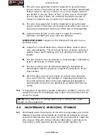
Page 15: ... The handle must not be bent or distorted and must rotate freely The locking pin must lock and hold the handle perpendicular to the arm Removable crank arm if present must lock positively into each of the drive hubs and be free of cracks bends or other damage Check that each handle on the crank arm is tight see Figure 9 Use Loctite262 or equivalent thread lock on the anchor screws if required to k...

Page 16: ...m body support connectors etc according to manufacturer s instructions 5 3 LIFELINE INSPECTION WIRE ROPE Inspect entire length of wire rope assembly starting at the hook Always wear protective gloves when inspecting wire rope A Inspect for broken wires by passing the wire rope through gloved hands flexing it every few inches to expose breaks Broken wires can be removed by bending the wire back and...

Page 17: ... The line must be free of chemical or heat damage indicated by brown discolored or brittle areas C The line must be free of ultraviolet damage indicated by discoloration and the presence of splinters and slivers on the rope surface D All of the above factors are known to reduce rope strength As a rule of thumb rope strength is reduced proportional to the cross sectional area of the rope damaged Da...

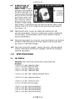
Page 18: ...LA 6 4 Store this equipment in a cool dry clean environment out of direct sunlight Avoid areas where chemical vapors exist Inspect after any period of extended storage 6 5 Clean and store body support support structure and associated system components according to separate instructions provided with that equipment 7 0 SPECIFICATIONS 7 1 MATERIALS Housing Cast Aluminum with powder coat paint finish...

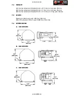
Page 19: ...vanced Digital Winch 27 lbs 12 2 kg plus lifeline 300 Series Advanced Digital Winch 27 5 lbs 12 4 kg plus lifeline 7 3 LOADS Maximum Working Load 450 lbs 204 kg Winch Mechanism Proof Load 5000 lbs 22 2 kN 7 4 DIMENSIONS A 100 SERIES B 200 SERIES C 300 SERIES netzerotools com netzerotools com ...

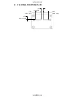
Page 20: ...20 406 10 3 mm 2 06 52 3 mm 75 19 mm 2 06 52 3 mm D UNIVERSAL MOUNTING PLATE netzerotools com netzerotools com ...

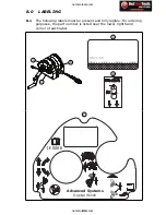
Page 21: ...resent and fully legible For ordering purposes the part number is listed near the lower right hand corner of each label B A C A B 5 TO 8 USES WD 40 9504598 REV C C 9504600 REV F Advanced Systems Digital Winch 0086 STOP netzerotools com netzerotools com ...

Page 22: ...________ DATE PURCHASED ______________DATE FIRST USED __________ INSPECTION DATE INSPECTION ITEMS NOTED CORRECTIVE ACTION MAINTENANCE PERFORMED Approved By Approved By Approved By Approved By Approved By Approved By Approved By Approved By Approved By Approved By Approved By Approved By Approved By Approved By netzerotools com netzerotools com ...

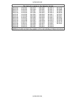
Page 23: ...8582 8518583 8518584 8518585 8518586 8518587 8518588 8518589 8518590 8518591 8518592 8518601 8518602 8518603 8518604 8518605 8518606 8518607 8518608 8518609 8518610 8518611 8518612 8518613 8518614 8518615 8518616 8518617 8518623 8518627 8518628 8518630 8518646 8518651 8518656 8518658 8518706 8524868 8526404 8526534 8530010 8530011 8530012 8530058 8530116 8530178 8530207 Additional model numbers ma...

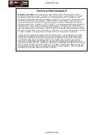
Page 24: ...ditional warranties or in any way increase the scope of this warranty CAPITAL SAFETY will not accept liability for defects that are the result of product abuse misuse alteration or modification or for defects that are due to a failure to install maintain or use the product in accordance with the manufacturer s instructions CAPITAL SAFETY S WARRANTY APPLIES ONLY TO THE END USER THIS WARRANTY IS THE...

Reviews: