9
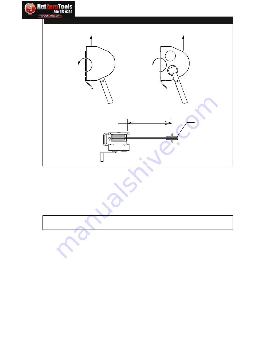
provided by DBI-SALA must meet the geometric requirements
shown in Figure 4. Position the support structure so the load and
the lifeline of the winch can be directed over the work area when
installed. For personnel use, do not position the support structure
where the worker will have to swing under the support structure
to reach the work area. Avoid positioning the support structure
where the working line may abrade against sharp edges.
IMPORTANT:
Position the winch and support structure in a location
which allows the operator to safely use the winch.
C. MOUNTING PLATE:
The Digital Winch is equipped with
a universal mounting plate. The universal mounting plate
is designed to attach to the quick mount bracket and the
advanced series winch mount bracket (see Figure 5) and will
accommodate most other support structures which meet the
requirements specified in section 3.3. See the support system
user manual for mounting information or contact DBI-SALA
for optional mounting kits. When attaching the winch to the
support, one of the attachment features (i.e., bolt or stud)
must capture the structural carrying handle.
D. WELDED INSTALLATIONS:
If welding the mounting bracket
to a support structure it is recommended that the welding be
done by a certified welder. Portions of the mounting bracket
that have been exposed due to welding should be painted or
otherwise protected from corrosion.
Figure 4 - Required Load Strength
1,900 ft-lbs
moment load
36 in. Min
Recommended
Directional
Sheave
2,500 lbs.
in direction of pull
Left Hand Retrieve
(cable feeds off top)
Right Hand Retrieve
(cable feeds off bottom)
Wire rope
directional sheaves
must have a
minimum tread
diameter of 2.5 in.
625 ft-lbs
moment load
2,500 lbs.
in direction of pull
netzerotools.com
netzerotools.com


