background image

10

4.0 USE


;

Never exceed the Capacity maximums specified in Table 1. Exceeding the stated capacity could collapse or tip the system, resulting 

in serious injury or death. 

4.1 

BEFOrE EACH USE:

 Verify that your work area and Personal Fall Arrest System (PFAS) meet all criteria defined in 

Section 2 and a formal Rescue Plan is in place. Inspect the Glyde-Saf HD FAS per the ‘

User

’ inspection points defined on 

the “

Inspection and Maintenance Log

” (Table 2). If inspection reveals an unsafe or defective condition, do not use the 

Glyde-Saf HD FAS. Remove the system from service and contact 3M Fall Protection regarding replacement or repair.


;

SAFE WORK AREA

: Figure 2 illustrates the Safe Work Area for the Glyde-Saf HD Fall Arrest System. The gray shading on the table 

designates safe working distances where the angle of the Lifeline is less than or equal to 30° from vertical. NEVER work at a Horizontal 

Distance (H) and Vertical Distance (V) that results in a calculated Vertical Fall Distance (F) exceeding the gray shaded values on the 

table in Figure 2.

4.2 

FALL ArrEST CONNECTIONS:

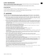
 Figure 9 illustrates application of the Glyde-Saf HD Fall Arrest System and its Fall 

Arrest Connections. The Glyde-Saf HD Fall Arrest System must always be used with a Full Body Harness and Fall Arrest 

subsystem. Trolleys within Trolley Rails travel back-and-forth inside the Trolley Rail halves. A Self-Retracting Lifeline (SRL) 

is connected to the eye on each Trolley. Connect the other end of the SRL to the back Dorsal D-Ring on the Harness. 


A Tag Line can be attached to the SRL Lifeline and used to retrieve the lifeline for connection to the user’s harness.


;

No more than one person, meeting the Capacity requirements specified in Table 1, shall be attached to each Trolley.

5.0 INSPECTION

5.1 

INSPECTION FrEQUENCY:

 The Glyde-Saf HD Fall Arrest System must be inspected at the intervals defined in Section 

1. Inspection procedures are described in the 

“Inspection Checklist” 

and

 “Maintenance Log” (Table 2)

. Inspect all other 

components of the Fall Protection System per the frequencies and procedures defined in the manufacturer’s instructions.

5.2 dEFECTS:

 If inspection reveals an unsafe or defective condition, remove the Glyde-Saf HD Fall Arrest System from 

service immediately and contact 3M Fall Protection regarding replacement or repair. Do not attempt to repair the 

Fall Arrest System.


;

Only 3M Fall Protection or parties authorized in writing by 3M Fall Protection may make repairs to this equipment.

5.3 

PrOdUCT LIFE:

 The functional life of the System is determined by work conditions and maintenance. As long as the 

product passes inspection criteria, it may remain in service.

6.0  MAINTENANCE, SERVICING, STORAGE

6.1 CLEANING:

 Periodically clean The System with a soft brush, warm water, and a mild soap solution. Ensure parts are 

thoroughly rinsed with clean water.


;

Although highly resistant to chemicals and environmental conditions, avoid contaminating the Flexiguard Anchorage System with 

acids, bitumen, cement, paint, cleaning fluids, etc. If the equipment contacts acids or other caustic chemicals, remove from service and 

wash with water and a mild soap solution. Inspect per Table 2 before returning to service.

6.2 SErVICE:

 Only 3M Fall Protection or parties authorized in writing by 3M Fall Protection may make repairs to this 

equipment. If the anchor has been subject to fall force or inspection reveals an unsafe or defective conditions, remove the 

anchor from service and contact 3M Fall Protection regarding replacement or repair.

Summary of Contents for DBI SALA FLEXIGUARD Glyde-Saf HD System

Page 1: ... 3M 2018 FLEXIGUARD Glyde Saf HD System Model Numbers 8530637 8530638 8530687 8530688 8530782 1 8530638 8530688 8530782 8530637 8530687 A B B C D USER INSTRUCTION MANUAL 5903679 Rev B ...

Page 2: ... 8 6 3 1 9 7 2 2 2 8 5 2 6 8 2 4 8 0 2 4 8 2 2 5 8 9 2 7 10 0 3 0 10 3 0 10 0 3 0 10 2 3 1 10 8 3 3 11 7 3 6 12 3 7 12 0 3 7 12 2 3 7 12 6 3 9 13 4 4 1 14 4 3 14 0 4 3 14 1 4 3 14 6 4 4 15 2 4 6 16 4 9 16 0 4 9 16 1 4 9 16 5 5 0 17 1 5 2 18 5 5 18 0 5 5 18 1 5 5 18 4 5 6 19 0 5 8 20 6 1 20 0 6 1 20 1 6 1 20 4 6 2 20 9 6 4 50 15 2 50 0 15 2 50 0 15 3 50 2 15 3 50 4 15 3 F V 4 0 ft 1 2 m 3 A 4 5 A B...

Page 3: ...3 6 A B A B 50 ft 15 2 m 6 ft 1 8 m 6 ft 1 8 m 7 8 ...

Page 4: ...4 9 ...

Page 5: ...s maintain 100 tie off when transferring between anchor points on the system Use caution when installing using and moving the system as moving parts may create potential pinch points Ensure proper lockout tagout procedures have been followed when applicable Only connect fall protection subsystems to the designated anchorage connection point on the system When drilling holes for assembly or install...

Page 6: ...ponent Materials Rating A Trolley Rail 8530637 8530687 length 10 ft 3 0 m 8530782 length 16 ft 2 in 4 9 m 8530638 8530688 length 20 ft 6 1 m Channel Steel Stiffener Beam Steel Stiffener Bar Steel 8530637 8530638 8530782 have E coat paint finish 8530687 8530688 have E coat followed by powder coat paint finish Maximum of two Trolley Rail joints per Glyde Saf HD Fall Arrest System See Figures 6 and 7...

Page 7: ...SRD LOCKING SPEED A clear path is required to assure positive locking of an SRD Situations which do not allow for an unobstructed fall path should be avoided Working in confined or cramped spaces may not allow the body to reach sufficient speed to cause the SRD to lock if a fall occurs Working on slowly shifting material such as sand or grain may not allow enough speed buildup to cause the SRD to ...

Page 8: ...may cause the gate to open B allowing the snap hook or carabiner to disengage from the connecting point C Self locking snap hooks and carabiners are required by ANSI Z359 and OSHA 2 10 MAKING CONNECTIONS Snap hooks and carabiners used with this equipment must be self locking Ensure all connections are compatible in size shape and strength Do not use equipment that is not compatible Ensure all conn...

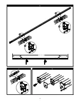
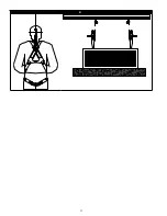
Page 9: ... can be bolted together to assemble a Glyde Saf HD Fall Arrest System Combined Trolley Rail sections can not exceed an overall length of 50 ft 15 2 m between intermediate brackets when assembled into a Glyde Saf HD Fall Arrest System The example in Figure 6 which shows two 10 ft Trolley Rails and one 20 ft Trolley Rail joined together to construct a 40 ft long Glyde Saf HD Fall Arrest System B Ali...

Page 10: ...son meeting the Capacity requirements specified in Table 1 shall be attached to each Trolley 5 0 INSPECTION 5 1 INSPECTION FREQUENCY The Glyde Saf HD Fall Arrest System must be inspected at the intervals defined in Section 1 Inspection procedures are described in the Inspection Checklist and Maintenance Log Table 2 Inspect all other components of the Fall Protection System per the frequencies and ...

Page 11: ...RAGE ARRESTING FORCE M A A F RATING OF 900 lbs 4 kN OR LESS AND MEET ANSI Z359 14 TYPE B OR Z359 13 RESPECTIVELY Retractable devices and shock absorbers must be installed maintained and used according to the manufacturer s instructions D 9509772 Rev A WARNING This man rated system is designed for a maximum of 2 PERSONS user capacity in accordance with the manufacturer s instructions Each user cann...

Page 12: ...ural defects or damage including bends cracks corrosion etc X Inspect fasteners that secure the joints between Trolley Rail Tracks Ensure fasteners are torqued to 60 ft lbs 81 Nm X Inspect all other fasteners Ensure that 3 4 in bolts are torqued to 130 ft lbs 176 Nm Re torque as necessary Trolley Remove and inspect Trolley for damage Trolley wheels should spin freely and show minimal wear Replace ...

Page 13: ......
Page 14: ... 7 29 Kitashinagawa Shinagawa ku Tokyo Phone 81 570 011 321 Fax 81 3 6409 5818 psd jp mmm com WEBSITE 3M com FallProtection I S O 9 0 0 1 FM534873 EU DECLARATION OF CONFORMITY 3M com FallProtection DOC U S PRODUCT WARRANTY LIMITED REMEDY AND LIMITATION OF LIABILITY WARRANTY THE FOLLOWING IS MADE IN LIEU OF ALL WARRANTIES OR CONDITIONS EXPRESS OR IMPLIED INCLUDING THE IMPLIED WARRANTIES OR CONDITIO...

Reviews: